Pumping unit driven by a linear electric motor

a linear motor and pumping unit technology, applied in the field of pumping units, can solve the problems of large volume of pumping units driven by rotating motors, high electrical energy consumption, complex structure, etc., and achieve the effect of reducing potential safety hazards, high pressure, and simplifying the structure of pumping units driven by linear motors

Inactive Publication Date: 2006-10-19
ZHOU XIAOXI
View PDF2 Cites 19 Cited by
  • Summary
  • Abstract
  • Description
  • Claims
  • Application Information

AI Technical Summary

Benefits of technology

[0005] Accordingly, an object of the present invention is to move the linear motor away from the wellhead device so as to resolve the above problems, i.e. the potential safety hazard occurs when the natural gas leaks; the linear motor occupies much space around wellhead because it is fixed above the wellhead device, thus causing many operations difficult; the linear motor causes the down hole casing to vibrate. In addition, the wellhead device can endure higher outside pressure without changing the original wellhead device in site. The headframe is replaced by a guide rail support of the linear motor.
[0008] The advantages of the present invention are as follows: an upper end of the mover of the linear motor is connected to one end of the chain, the chain passes the chain wheel and is connected to the pumping slick rod at the other end thereof. The wellhead device and the pumping slick rod are away from the linear motor, and the linear motor is moved away from the above of the wellhead, when leakage of the natural gas occurs, the leaked natural gas can not enter the linear motor directly, thus eliminating the potential safety hazard. The linear motor is not disposed above the wellhead device, and the original wellhead device can be used, so that it is still convenient for a worker to operate around the wellhead by comparison with the pumping unit driven by a rotating motor in the prior art. In addition, even if the linear motor generates vibration during operating, the downhole casing will not be affected and the wellhead device can endure high pressure. The structure of the pumping unit driven by a linear motor is also simplified by replacing the headframe by the guide rail support of the linear motor.

Problems solved by technology

The pumping unit driven by a rotating motor is large in volume, complex in structure and high in electrical energy consumption.
The stators of the linear motor and the limit posts are fixed to the wellhead device, the mover of the linear motor causes the wellhead device to vibrate while it moves, thus causing leakage of crude oil and natural gas from the wellhead device.
If leakage of the natural gas occurs, since the linear motor is fixed above the wellhead device, the leaked natural gas will enter the linear motor directly, thus causing potential safety hazard.
The linear motor is fixed above the wellhead device so that it occupies a space around the wellhead, operations such as replacement of the packing set box and the packing set will become difficult.
If the linear motor is fixed above the wellhead, a wellhead device which can endure higher outside pressure should be designed renewedly to match the linear motor, this will increase the cost of the pumping unit.

Method used


Image

  • Pumping unit driven by a linear electric motor
  • Pumping unit driven by a linear electric motor

Examples


embodiment 1

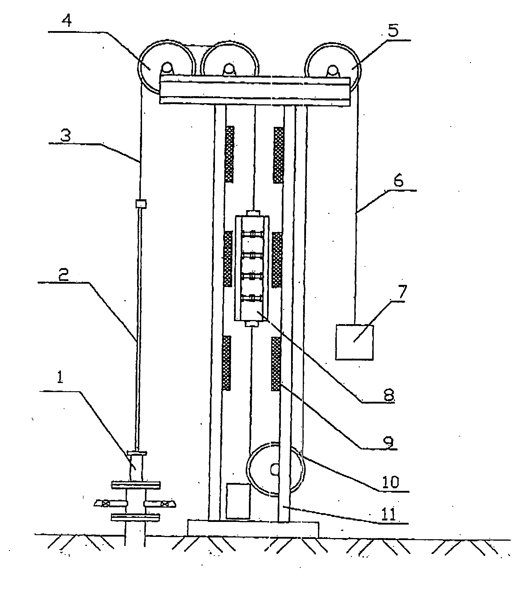
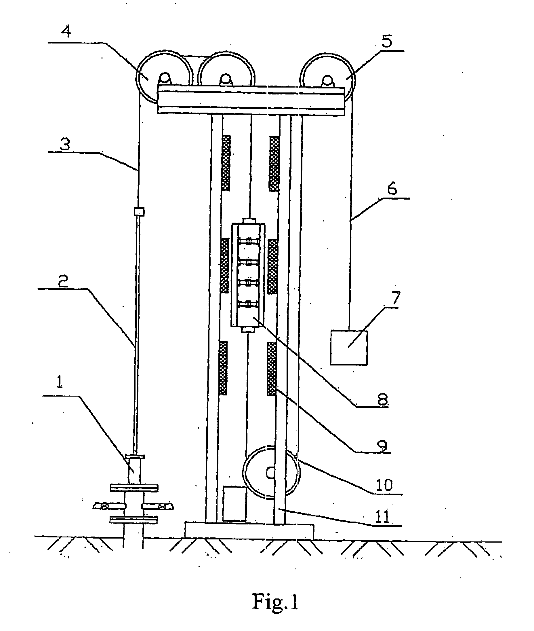
[0013] The guide rail support 11 of the pumping unit driven by a linear motor is formed by two channel beams, between the channel beams are provided with crossbeams, thus forming a frame structure. The frame structure can be formed by the channel beams and the crossbeams through welding or screwed connection. In order to improve stability of the frame structure, the guide rail support can be formed by flanged beams and steel plates instead of the channel beams and the crossbeams through welding. Four guide slide ways formed by angle bars through welding are provided on inner sides of the guide rail support. The guide slide ways are used for controlling sliding movement of the mover 8 of the linear motor, the mover 8 is connected to one end of the counterweight chain 6 at a lower end thereof, and the counterweight chain 6 passes a bottom chain wheel 10 disposed at the bottom of the guide rail support and a top chain wheel 5 disposed at the top of the support sequentially and is then ...

embodiment 2

[0014] The guide rail support 11 of the pumping unit driven by a linear motor in the embodiment 2 is substantially identical with that in the embodiment 1, except for the following aspects: there are two pulleys 4 at the top of the guide rail support 11, the diameter of the pulleys is 500 mm, the chain 3 is replaced by a wire rope 3 whose diameter is 25 mm, and the counterweight chain 6 is also replaced by a counterweight wire rope 6. One end of the counter weight wire rope 6 is connected to a lower end of the mover 8 of the linear motor, and the other end thereof passes the bottom chain wheel 10 disposed at bottom of the guide rail support and the top chain wheel 5 disposed at top of the support sequentially and is then connected to the counterweight 7. In other words, in the embodiment 2, the chain and the counterweight chain in the embodiment 1 are replaced by wire ropes, and the chain wheel, the bottom chain wheel and the top chain wheel in the embodiment 1 are replaced by pulle...


PUM


Abstract

The present invention disclose a pumping unit driven by a linear motor, comprising a guide rail support in the form of a frame structure, a mover of the linear motor provided with slide blocks, said slide blocks engages guide slide ways used for said mover and mounted on inner sides of said guide rail support, six stators of the linear motor, said stators are mounted on inner sides of said guide rail support, a chain wheel disposed at the top of said guide rail support, a chain, said chain is connected to an upper end of said mover of the linear motor at one end, passes said chain wheel and is then connected to a pumping slick rod of a wellhead device at the other end thereof, a counterweight, and a counterweight chain, said counterweight chain is connected to a lower end of said mover at one end, passes a bottom chain wheel disposed at the bottom of the guide rail support and a top chain wheel disposed at the top of the guide rail support sequentially and is then connected to said counterweight at the other end thereof. Since the pumping unit is disposed at a side of the wellhead, it is convenient for operations and eliminates possibility of occurring of accident without changing the original wellhead.

Description

CROSS-REFERENCE TO RELATED APPLICATIONS [0001] This application relates to and claims priority from PCT / CN02 / 00111 filed Feb. 25, 2002 and parent Application Serial No. 01204055.X filed Feb. 26, 2001.FIELD OF THE INVENTION [0002] The present invention generally relates to a pumping unit, more particularly to an oil well pumping unit disposed on the ground and driven by a linear motor. BACKGROUND ART [0003] Presently, most of oil well pumping units are driven by a rotating motor vie a speed reducer and a conversion device for converting rotary movement into linear movement, thereby driving the pumping slick rod and the pumping rod to reciprocate up and down and driving the downhole oil extraction pump to extract oil. The pumping unit driven by a rotating motor is large in volume, complex in structure and high in electrical energy consumption. The Chinese Utility Model No. 96217 638.9 disclosed a pumping unit driven by a linear motor. The technical scheme of the Utility Model is that ...

Claims


Application Information

Patent Timeline
Patent Type & Authority Applications(United States)
IPC IPC(8): F04B35/04E21B43/12F04B17/04F04B47/02F04B47/14
CPCE21B43/126F04B47/14F04B47/02F04B17/042
Inventor ZHOU, XIAOXI
Owner ZHOU XIAOXI
Why Eureka
Try Eureka