Continuously variable dual mode transmission

Inactive Publication Date: 2006-10-19
EATON INTELLIGENT POWER LIMITED
View PDF21 Cites 157 Cited by
  • Summary
  • Abstract
  • Description
  • Claims
  • Application Information

AI Technical Summary

Benefits of technology

[0005] The inventive system beneficially provides a CVT and a CVT control system which operates the CVT in a power splitting mode at high vehicle speeds. This is accomplished by operating the vehicle in a variator-only mode at low vehicle speeds, and operating in a power splitting mode at high speeds. This arrangement is particularly beneficial for vehicles which spend extended periods of time operating in the high speed range, as the cumulative loading on the variator is less than if the CVT operated in a variator only mode at high speeds and a power splitting mode at low speeds.
[0006] A dual mode continuously variable transmission for use with motor vehicles includes a transmission input shaft, a transmission output shaft, and a variator disposed between the transmission input shaft and the transmission output shaft. A mixer gear set is operably disposed between the transmission input shaft and the variator output shaft. A clutching element is operably disposed between the input shaft the mixer gear set. An electronic control unit is operably connected to the variator and to the clutching element. The variator is configured to continuously vary a ratio of input torque to output torque between the variator shafts responsive to commands from the electronic control unit. The variator input shaft is drivingly connected to the input shaft and the variator output shaft is drivingly connected to the output shaft. The clutching element selectively connects and disconnects the input shaft and the mixer gear set to operate the transmission in a power splitting mode of operation and a variator only mode of operation. The electronic control unit is configured to include logic rules for controlling the transmission. The logic rules include rules by which the clutching element maintains the transmission in a variator-only mode of operation in a first vehicle speed range, and maintains the transmission in a power splitting mode of operation in a second vehicle speed range greater than the first vehicle speed range.
[0007] A dual mode continuously variable transmission for use with motor vehicles includes a transmission input shaft, a transmission output shaft, and a variator disposed between the transmission input shaft and the transmission output shaft. A planetary mixer gear set is operably disposed between the transmission input shaft and the variator output shaft. A grounded element is rotatively fixed relative to a transmission housing. A first clutching device is operably disposed between the transmission input shaft and the planetary mixer gear set. The second clutching device is operably disposed between the ring gear and the grounded element. An electronic control unit is operably connected to the variator and to the clutching elements. The variator is configured to continuously vary a ratio of input torque to output torque between the variator shafts responsive to commands from the electronic control unit. The variator input shaft is drivingly connected to the transmission input shaft and the variator output shaft is drivingly connected to the transmission output shaft. The planetary mixer gear set includes a ring gear rotatable about a first axis, a sun gear rotatable about the first axis and drivingly connected to the variator output shaft, and a carrier drivingly connected to the transmission output shaft and rotatable about the first axis with a plurality of planet gears in mesh with both the sun gear and the ring gear. The first clutching device is disposed and configured so as to selectively connect the input shaft with the ring gear to achieve a power splitting mode of operation. The second clutching device is disposed and configured to selectively connect the ring gear and the grounded element to achieve a variator-only mode of operation. The electronic control unit is configured to include logic rules for controlling the transmission, the logic rules including rules by which the clutching element maintains the transmission in the variator-only mode of operation in a first vehicle speed range and maintains the transmission in the power splitting mode of operation in a second vehicle speed range greater than the first vehicle speed range.
[0008] A dual mode continuously variable transmission for use with motor vehicles includes a transmission input shaft, a transmission output shaft

Problems solved by technology

The large number of gears means that there is a frequent need for shifting.
However, even with a large number of ratios, and automated shifting, the engine speed varies with the speed of the vehicle when the vehicle is in a given gear ratio.
This means that the engine's operating parameters must be compromised to accommodate the anticipated range of engine operating speeds.
Shifting decreases the operating efficiency of the vehicle, as there can is typically a dip in vehicle speed during the shift when the engine is momentarily disconnected from the drive wheels, and a subsequent need to bring the vehicle back to its target speed.
However, pulley chain variators available today generally have a limited torque capacity and, for a heavy duty vehicle such as a commercial truck, would be unable to sustain all of the engine power all of the time.
One known approach of the limitations to the use of CVTs employing chain and pulley type variators has been to reduce the duty cycle to which such variators are exposed.
However, for certain applications such as line-haul trucks where the vehicle spends most of its driving time at relatively elevated speeds, operating in the variator only mode for long distances has the undesired effect of reducing fuel economy.

Method used


Image

  • Continuously variable dual mode transmission
  • Continuously variable dual mode transmission
  • Continuously variable dual mode transmission

Examples


first embodiment

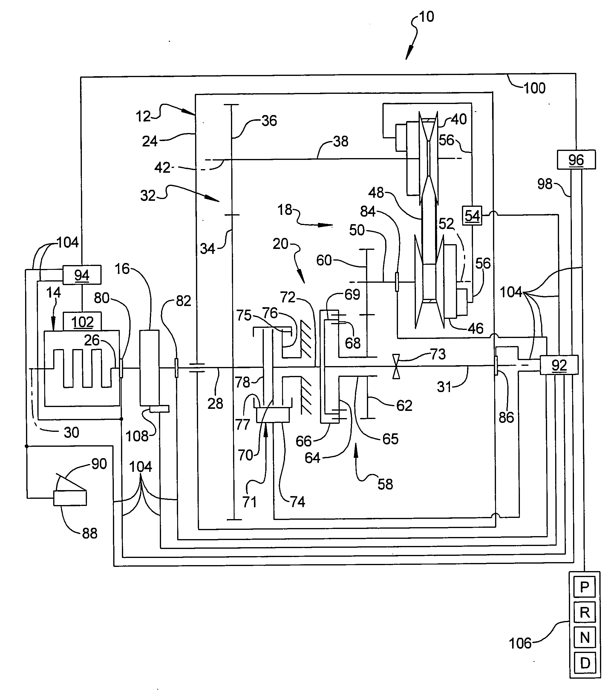
[0017] Referring to FIG. 1, a vehicle drivetrain 10 including a continuously variable transmission 12 and an electronically controlled internal combustion engine 14 is illustrated. Continuously variable transmission 12 is connected with engine 14 by a normally engaged master friction master clutch 16. Transmission 12 includes a variator 18 and a planetary mixer gear set 20. Mixer gear set 20 may alternatively characterized as a differential gear set. Variator 18 and planetary mixer gear set 20 are disposed in and supported by a transmission case or housing 24. A somewhat similar system is disclosed in U.S. patent application Ser. No. 10 / 695,314 filed Oct. 28, 2003 and published on Jul. 1, 2004 as Publication No. US 2004 / 0127321, which is hereby incorporated by reference into this application.

[0018] Engine crankshaft 26 of engine 14 is selectively drivingly connected by master friction clutch 16 to a transmission input shaft 28. Input shaft 28 rotates about a first axis of rotation ...

second embodiment

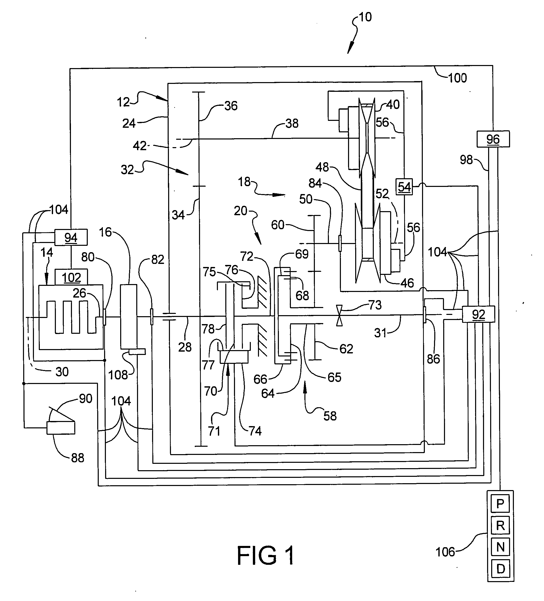
[0056]FIG. 2 shows a second embodiment of the invention. Except as indicated otherwise, the elements of the second embodiment are common with those of the first embodiment. All reference numerals in FIG. 2 correspond to elements having the same names as the elements in FIG. 1, except that the reference numerals in FIG. 2 are greater by 200, unless otherwise indicated. The embodiment of FIG. 2 is similar to the embodiment of FIG. 1 except that no jaw clutch is provided on output shaft 231 to fix sun gear 264 to output shaft 231. Instead, a jaw clutch 273 is provided on the variator output shaft 250. Jaw clutch 273 selectively engages one of a reverse output drive gear 259 and a forward output drive gear 260. A transmission controller and an actuating element, not shown, but as described below in the description of the third embodiment, is used to control clutch 273. A reverse idler gear 261, rotatable about an axis parallel to axis 230, is provided between reverse output drive gear 2...

third embodiment

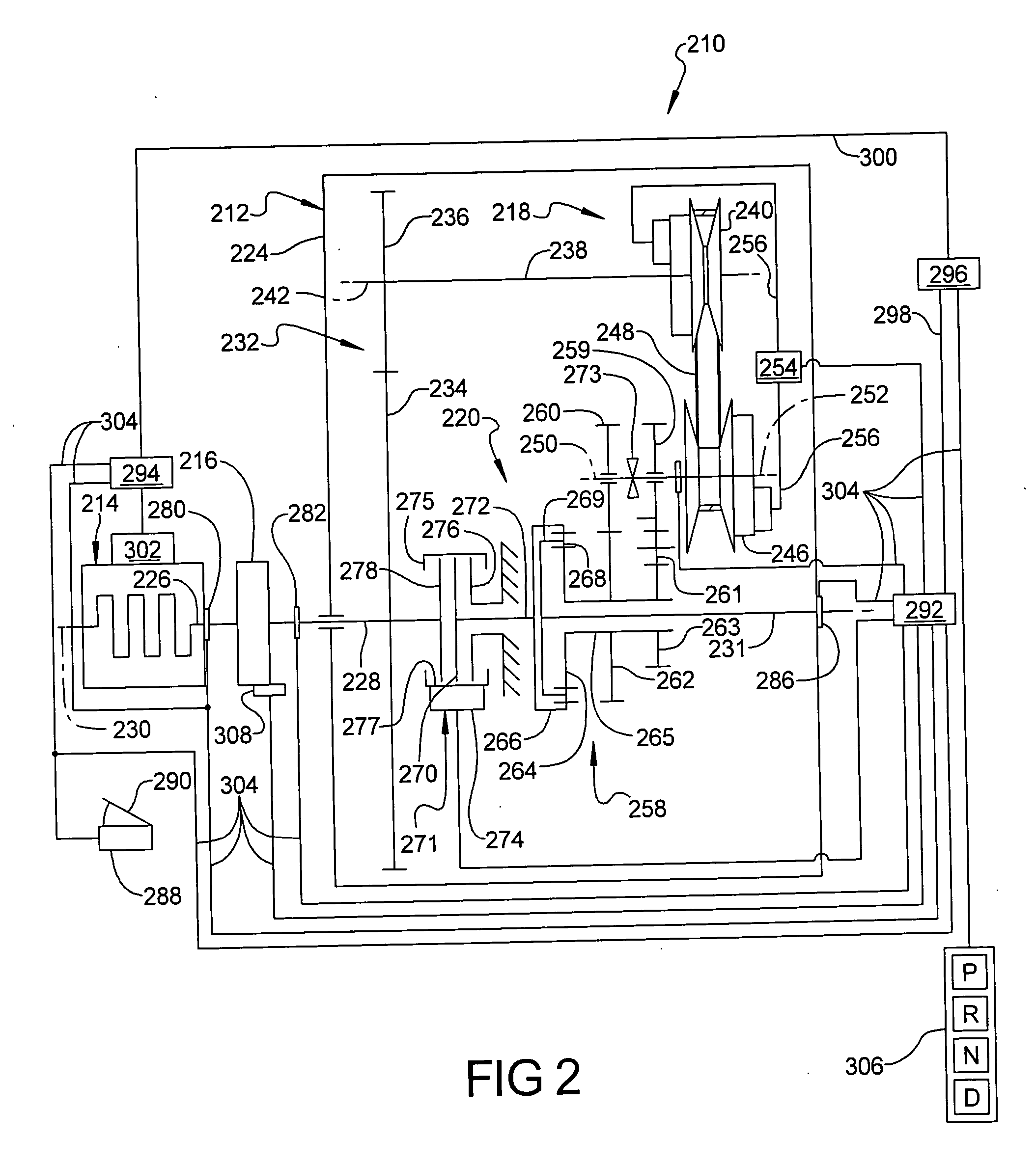
[0062]FIG. 3 shows a third embodiment of the invention. Except as indicated otherwise, the elements of the third embodiment are common with those of the first embodiment. All reference numerals in FIG. 3 correspond to elements having the same names as the elements in FIG. 1, except that the reference numerals in FIG. 3 are greater by 400, unless otherwise indicated. A CVT 412 incorporates a countershaft gear unit 422 in combination with a variator 418 and a planetary mixer gear set 420 like that found in FIG. 1. Gear unit 422 and the features used to control it are found in automated mechanical transmissions sold by Eaton Corporation, the assignee of this invention, under the name AutoShift®. Gear unit 422 is similar to the transmissions shown in U.S. Pat. Nos. 3,105,395, 3,283,613 and 4,754,655, the disclosures of which are hereby incorporated by reference. A benefit of incorporating gear unit 422 into CVT 412 is that it provides CVT 412 with a much broader torque ratio range than ...


PUM


Abstract

A dual mode continuously variable transmission for use with motor vehicles includes a transmission input shaft, a transmission output shaft, and a variator disposed between the transmission input shaft and the transmission output shaft. A mixer gear set is operably disposed between the transmission input shaft and the variator output shaft. A clutching element is operably disposed between the input shaft the mixer gear set. The variator is configured to continuously vary a ratio of input torque to output torque between the variator shafts responsive to commands from an electronic control unit. The variator input shaft is drivingly connected to the input shaft and the variator output shaft is drivingly connected to the output shaft. The clutching element selectively connects and disconnects the input shaft and the mixer gear set to operate the transmission in a power splitting mode of operation and a variator only mode of operation. An electronic control unit incorporates logic rules by which the clutching element maintains the transmission in a variator-only mode of operation in a first vehicle speed range, and maintains the transmission in a power splitting mode of operation in a second vehicle speed range greater than the first vehicle speed range.

Description

RELATED APPLICATIONS [0001] This application claims the benefit of U.S. Provisional Application No. 60 / 671,917, filed Apr. 15, 2005 entitled “Continuously Variable Dual Mode Transmission”, which is incorporated herein by reference in its entirety.FIELD OF THE INVENTION [0002] The present invention relates to continuously variable transmissions or CVTs used to transform torque and speed from initial values on an input side to second values on an output side. In particular, the present invention relates to the use of CVT in a dual mode fashion, where in a first mode, all of the power passes through the CVT and in a second mode, the power is split between the CVT and fixed ratio gear set. BACKGROUND OF THE INVENTION [0003] Trucks, particularly heavy duty trucks, commonly employ multiple speed counter-shaft type mechanical transmissions having up to at least 18 different torque multiplication ratios. The large number of ratios is needed to enable a fully loaded truck to perform a variet...

Claims


Application Information

Patent Timeline
IPC IPC(8): F16H37/02
CPCF16H37/0833F16H37/0846F16H61/66259F16H2037/0886F16H2061/6601F16H2300/14F16H2037/088
Inventor MORSCHECK, TIMOTHY J.STINE, ALAN C.REYNOLDS, JOSEPH D.OLIVER, JAMES L.
Owner EATON INTELLIGENT POWER LIMITED
Why Eureka
Try Eureka