
Device having a self sealing fluid port

a fluid port and self-sealing technology, applied in the field of devices having fluid ports, can solve the problem of still needing to be handled by the cap

Inactive Publication Date: 2006-10-19
ROCHE MOLECULAR SYST INC
View PDF27 Cites 11 Cited by
  • Summary
  • Abstract
  • Description
  • Claims
  • Application Information

AI Technical Summary

Benefits of technology

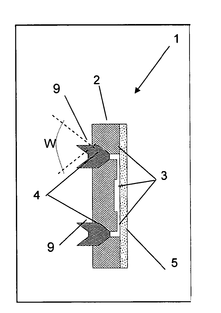
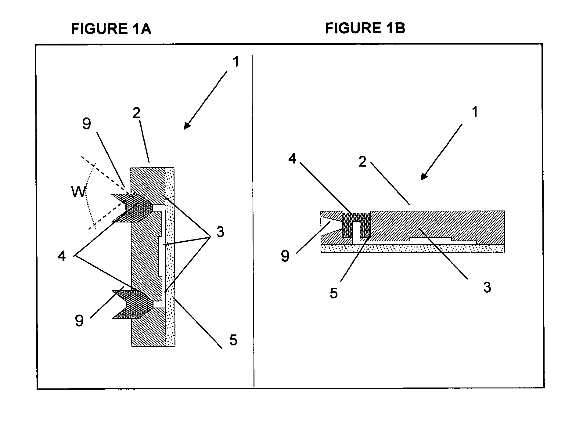
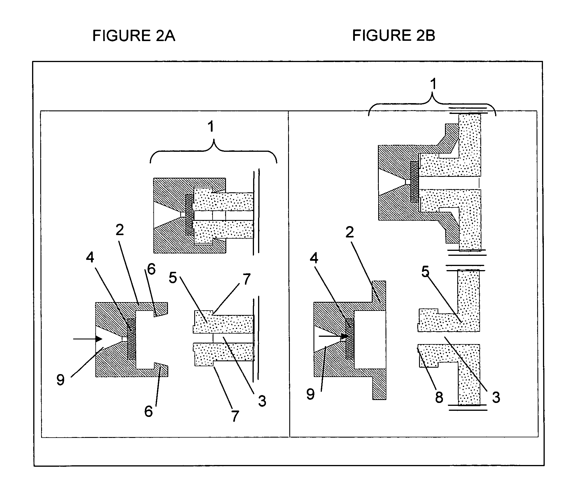
[0138] An advantage of the device according to the present invention is that the interface between the device and the closure of the device is very tight. This allows the application of high pressure to the inside of the device, for example, when the cavity within the device has channels of very small dimension or / and the use of liquids, which tend to clot during transport or reaction in a micro fluidic device. An advantage of the manufacturing device is that using this method it is possible to provide a device which is tightly sealed. The device according to the invention can be very advantageously used in systems for analysis of a liquid, as due to the tightness of the sealing, the instrument is better protected from contamination by fluid escaping the device, and on the other hand the interior of the device is protected from contamination from the ambience. Using the device according to the invention furthermore leads to increased convenience in analyses, as analysis can be automated using automated fluid delivery through a rigid fluid actuator. In addition, particularly for small devices, manufacturing gets more simple and reliable.

Problems solved by technology

However, those assemblies still need handling of the cap prior to the analysis, i.e. closing the tube using the cap after sample and reagents were added.
Those tube based devices all have the drawback that they only have one fluid port, through which both introduction and removal of liquid has to be made.

Method used


Image

  • Device having a self sealing fluid port
  • Device having a self sealing fluid port
  • Device having a self sealing fluid port

Examples


first embodiment

[0035] The size of the device according to the invention is mainly determined by the amount of fluid to be held or processed in the device and by the kind and number of steps to be performed. In a first embodiment, the device is used as a means to isolate components of the fluid. The component(s) to be isolated will be retained in the device, while the remainder of the liquid is allowed to exit the device. In this case, the volume of the liquid may exceed the volume of the cavity in the device. This allows the device to be comparably small. For this embodiment, the total volume assumed by the device will be preferably between 100 μl and 10 ml.

second embodiment

[0036] In a second embodiment, which is preferred, the device will be only slightly larger than the volume of the fluid and of any reagents intended to be reacted with the fluid. As volumes of fluids preferably have a volume of more than 0.1 μl, preferably between 0.2 μl and 1 L, the volume of the device will exceed 200 μl, preferably be between 200 μl and 1.1 L, and most preferably will be between 500 μl and 110 ml. Optionally the device has a substantially flat structure, i.e. in its main part it has a thickness of less than 50 mm, preferably of between 0.2 and 10 mm, a length and width of less than 300 mm, preferably of between 2 and 150 mm. If parts of the device need larger thickness, this part may exceed over the substantially flat structure.

[0037] For receiving and maintaining a fluid, the device has a body, which further contains one or more cavities, which temporarily or continuously receive or / and maintain the fluid or a fluids derived therefrom.

[0038] Conveniently, the b...


PUM

PropertyMeasurementUnit
Fractionaaaaaaaaaa
Electric chargeaaaaaaaaaa
Nanoscale particle sizeaaaaaaaaaa

Abstract

Manufacture of a device having a body comprising a cavity with a fluid port made from an elastomeric material adhering to the body is disclosed. The device can be used advantageously in reliable analyses in automated procedures.

Description

FIELD OF THE INVENTION [0001] The present invention relates to a device having a self sealing fluid port, methods for manufacturing such a device, a system for analysis of a fluid using said device, the use of said device in analyses of fluids and a method of analysis using said device. BACKGROUND OF THE INVENTION [0002] Particularly in analytical laboratories there is a great interest in conducting analyses in a convenient, safe and reliable way. Particular problems are the contamination of reagents, samples and devices for performing an analysis by the environment and the contamination of the environment by reagents or samples. [0003] Therefore devices have been proposed for the storage, the delivery and processing of a sample and / or reagents. [0004] In a simple form, such devices are single cavity devices, based on tubes, having a substantially conical or / and cylindrical form, having a single fluid port, which after introduction of the sample and the reagents is closed by a cap a...

Claims


Application Information

Patent Timeline
IPC IPC(8): A61B5/00B81C99/00
CPCB01L3/502707B29C66/53461B01L3/50825B01L7/52B01L2200/027B01L2200/12B01L2300/042B01L2300/044B01L2300/0816B01L2300/0887B29C45/1676B29C65/02B29C65/08B29C65/16B29C65/1606B29C65/1616B29C65/1619B29C65/48B29C65/58B29K2021/003B29K2023/06B29K2023/12B29K2025/00B29K2033/12B29K2069/00B29K2101/12G01N35/1079B01L3/502715B29C66/71G01N1/10G01N35/00G01N37/00
Inventor ELSENHANS, OLIVIERSAROFIM, EMADSAVATIC, GORAN
Owner ROCHE MOLECULAR SYST INC
Learn More