

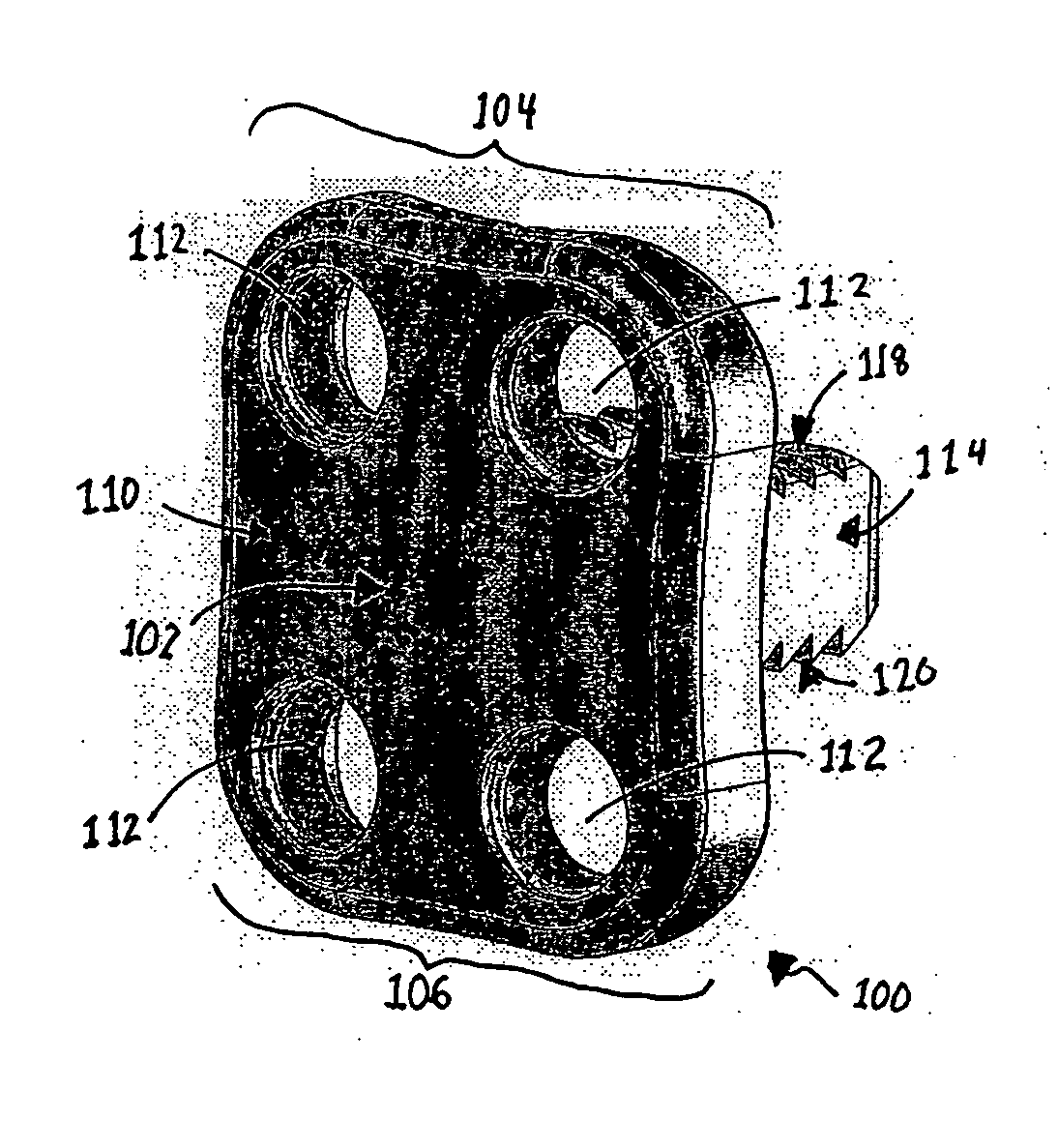
Flanged interbody fusion device with locking plate
a fusion device and locking plate technology, applied in the field of spinal fixation systems and methods, can solve problems such as spinal instability, pain and instability, degenerative changes in bones,
- Summary
- Abstract
- Description
- Claims
- Application Information
AI Technical Summary
Benefits of technology
Problems solved by technology
Method used
Image

Examples
Embodiment Construction
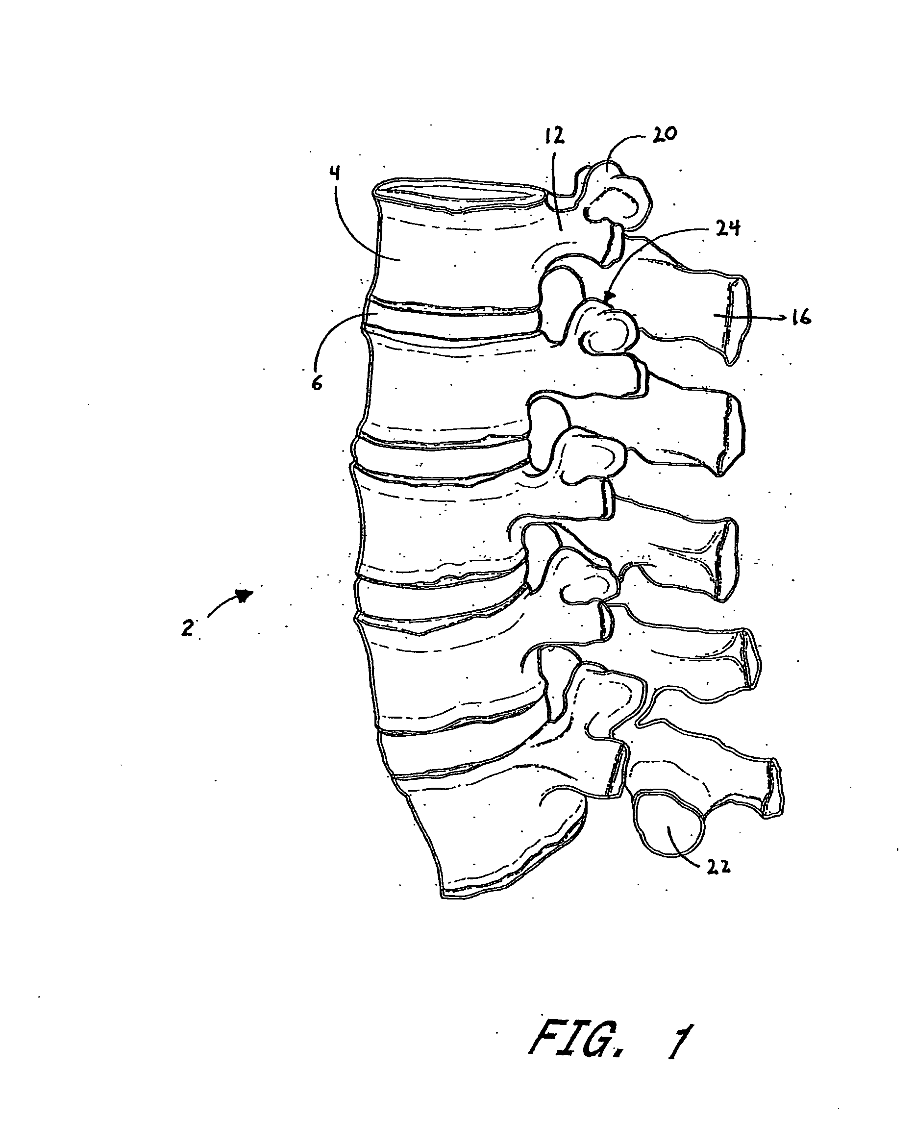
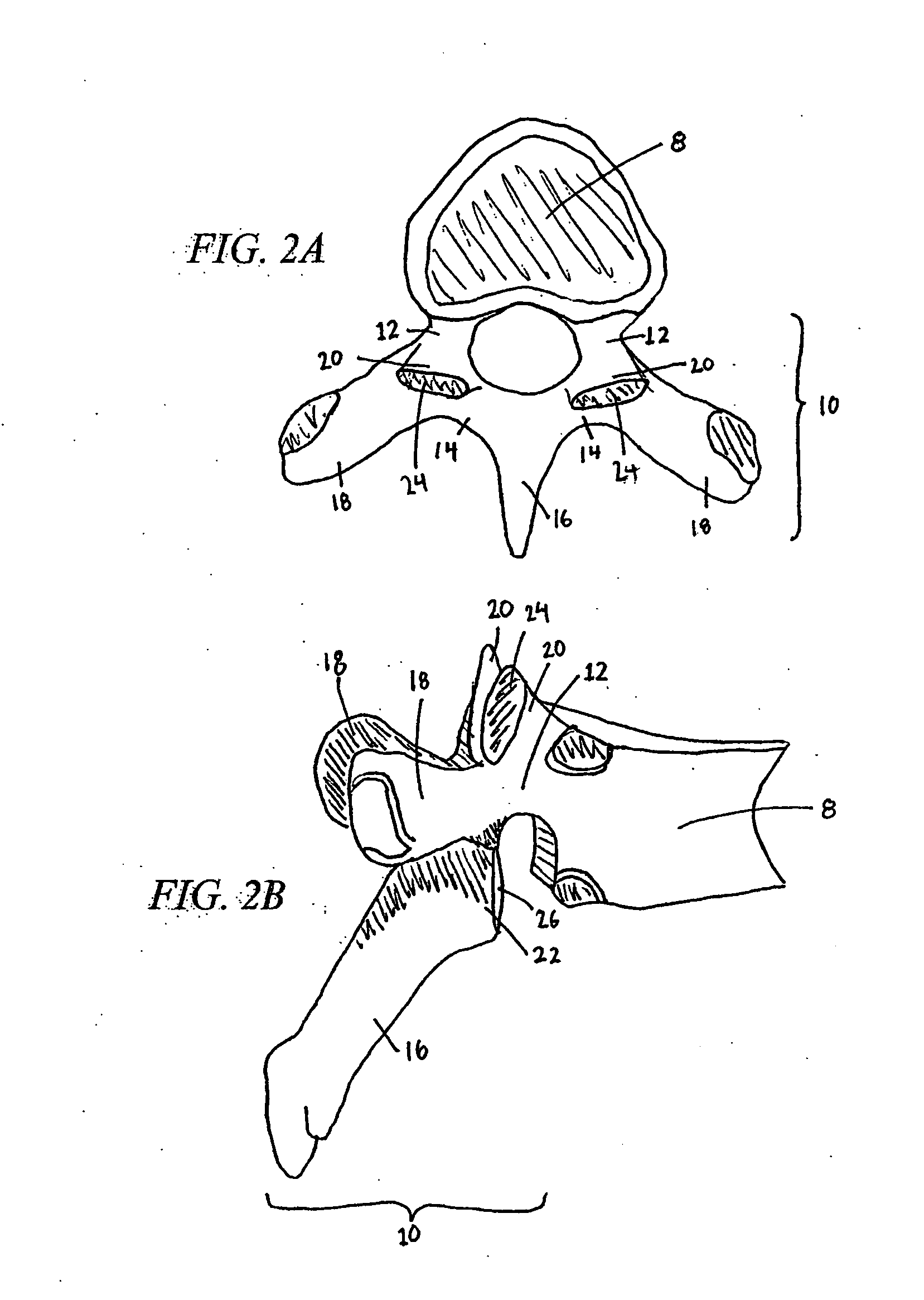
[0094] Advancing age, as well as injury, can lead to degeneration in the bones, discs, joints, and ligaments of the spine producing pain from nerve root compression. Under certain circumstances, alleviation of pain can be provided by performing a spinal fusion. Spinal fusion is a procedure that involves joining two or more adjacent vertebrae so that they no longer are able to move relative to each other.
[0095] In existing spinal fusion implants there have also been problems with loosening and backing out of screws into the patient's throat area. Backout is the exhibited tendency of bone screws, which affix the bone plate to the bone(s), to loosen with respect to both the plate and bone, resulting in poor fixation, fusion and ultimately, healing. Essentially, this loosening of the bone screw causes the screw to work itself out of the bone into which it is implanted. This results in the bone plate being poorly fixed in place thus becoming devoid of its fixation capabilities. Usually,...
PUM
| Property | Measurement | Unit |
|---|---|---|
| height | aaaaa | aaaaa |
| height | aaaaa | aaaaa |
| height | aaaaa | aaaaa |
Abstract
Description
Claims
Application Information