Eureka AIR delivers breakthrough ideas for toughest innovation challenges, trusted by R&D personnel around the world.

Radial tire for an airplane and method of manufacturing radial tire for an airplane

Active Publication Date: 2006-10-26
BRIDGESTONE CORP
View PDF2 Cites 12 Cited by
  • Summary
  • Abstract
  • Description
  • Claims
  • Application Information

AI Technical Summary

Benefits of technology

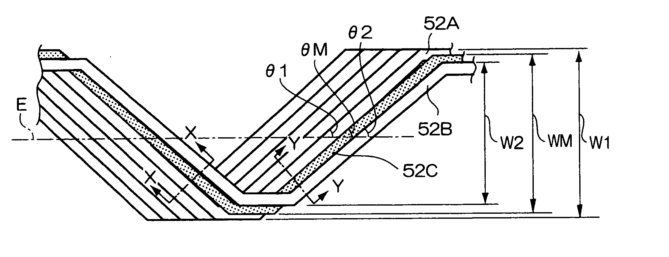
[0009] In view of the aforementioned, the present invention provide a radial tire for an airplane in which there is little strain of the belt layers and which has high durability, and a method of manufacturing the radial tire for an airplane.
[0012] By providing the intermediate cord portion in this way, the gap and the overlapping between cords in a vicinity of the switching of the angle can be made to be small. In this way, the rubber between the cords within the belt after vulcanization can be ensured, strain can be made small, and durability can be improved.
[0016] In order to make the gap and the overlapping between adjacent cords small, the intermediate cord portion is preferably wound over one circumference or more, and, from the standpoint of the balance between improving durability and decreasing weight, the intermediate cord portion is preferably wound over less than or equal to 10 circumferences.
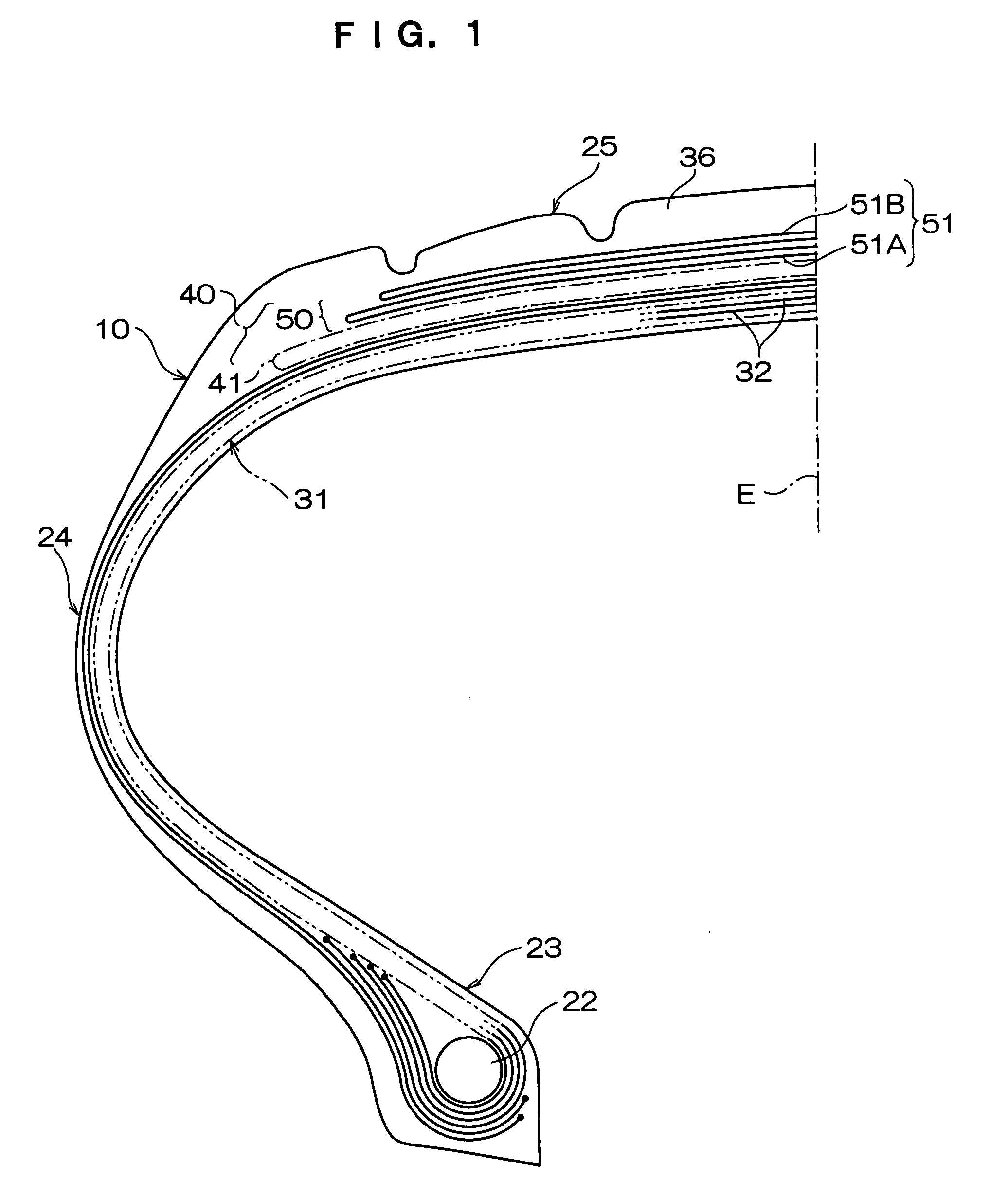
[0018] Here, “inextensible” means elongation at the time of rupture being less than 10%, and “high elastic modulus” means having a tensile rupture strength of greater than or equal to 6.3 cN / dtex. By providing a spiral belt structured by inextensible, high elastic modulus cords in this way, it is possible to structure a tire for an airplane which has good durability.
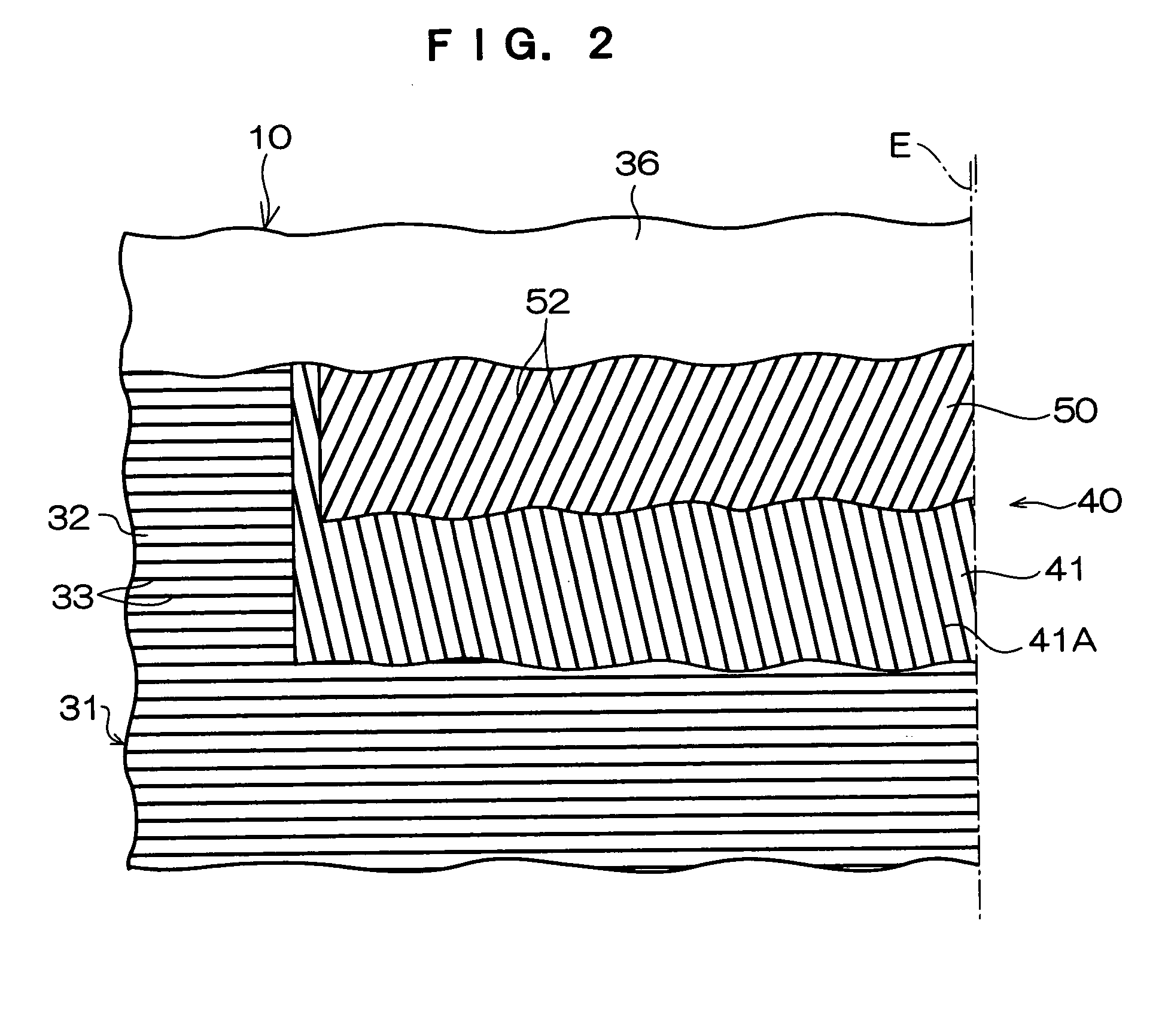
[0020] By making the changes in the members at the time of vulcanization molding be small in this way, the rubber gauge between the plural belt layers which are laminated can be ensured.

Problems solved by technology

Therefore, even in cases in which the angle of inclination of the cords with respect to the tire equatorial plane is made to be small in an attempt to improve the total strength of the belt, the shearing strain between layers at the ends of the belt is low, and it is difficult for belt end separation to arise.
Therefore, after vulcanization as well, the aforementioned gap H and overlapping I remain, and this is a cause of an increase in strain.
Such strain is an impediment to improving the durability of the pneumatic radial tire for an airplane.

Method used


Image

  • Radial tire for an airplane and method of manufacturing radial tire for an airplane
  • Radial tire for an airplane and method of manufacturing radial tire for an airplane
  • Radial tire for an airplane and method of manufacturing radial tire for an airplane

Examples


examples

[0050] Two types of test tires relating to the present invention (Examples 1, 2) and one type of test tire relating to a comparative example (Comparative Example 1) were readied, and evaluation of durability was carried out in accordance with an internal drum test. The intermediate cord portion 52C was wound-around twice in the tire of Example 1, the intermediate cord portion 52C was wound-around five times in the tire of Example 2, and the intermediate cord portion 52C was not provided in the tire of Comparative Example 1. Note that, for all of the tires, tires were used which has six layers of spiral belts, four layers of zigzag endless belts, and a tire size of 1270×455R22 30PR.

TABLE 1ComparativeExample 1Example 2Example 1spiral belts6 layers6 layers6 layerszigzag endless4 layers4 layers4 layersbeltsintermediate2 times5 timesnonecord portionrunning distance1.541.671.0

[Test Conditions][0051] testing internal pressure: 90% of normal internal pressure (1510 kPa) [0052] testing lo...


PUM


Abstract

In a belt layer structured by a plurality of zigzag endless belts which are layered in a tire radial direction and are folded-over at both ends in a tire widthwise direction and are disposed uniformly over an entire region, an angle θ1 of an inner side cord portion and a tire equatorial plane, an angle θ2 of an outer side cord portion and the tire equatorial plane, and an angle θM of an intermediate cord portion and the tire equatorial plane, are θ1>θM>θ2.

Description

CROSS-REFERENCE TO RELATED APPLICATION [0001] This application claims priority under 35 USC 119 from Japanese Patent Application Nos. 2005-123839, and 2006-088357, the disclosure of which is incorporated by reference herein. BACKGROUND OF THE INVENTION [0002] 1. Field of the Invention [0003] The present invention relates to a radial tire for an airplane which is used in airplanes such as passenger jet planes or the like, and to a method of manufacturing the radial tire for an airplane. [0004] 2. Description of the Related Art [0005] Conventionally, structures such as disclosed in WO 2003 / 061991 have been known as a radial tire for an airplane. As shown in FIG. 7, the radial tire for an airplane disclosed in WO 2003 / 061991 has an endless zigzag belt ply in which cords, which extend in the circumferential direction while zigzagging by being folded over at both ends of the ply, are embedded substantially uniformly at the entire region. [0006] In a radial tire having such an endless zig...

Claims


Application Information

Patent Timeline
IPC IPC(8): B60C9/18
CPCB29D30/3028B29D30/3035Y10T152/10783B60C9/263B60C2200/02B60C9/2204
Inventor TAKANAMI, TAKESHI
Owner BRIDGESTONE CORP
Why Eureka
Eureka Blog
Learn More