Separation of drilling mud emulsions

a technology of emulsion and drilling mud, which is applied in the separation process, sedimentation settling tank, and borehole/well accessories. it can solve the problems of mud contamination with debris, difficult to break or resolve emulsions,

Inactive Publication Date: 2006-10-26
BETZ LAB INC
View PDF14 Cites 31 Cited by
  • Summary
  • Abstract
  • Description
  • Claims
  • Application Information

AI Technical Summary

Problems solved by technology

During drilling operations, the muds may become contaminated with debris that is carried by the drilling bits and with liquids such as water and brines that enter the drilling hole from above or by leaching into the hole through subterranean locations.
These emulsions become

Method used


Image

  • Separation of drilling mud emulsions
  • Separation of drilling mud emulsions

Examples


examples

[0045] Tests were conducted with centrifugal separation of the inverted drilling mud emulsion samples. The tests were conducted without treatment and with the cationic flocculant (I) and cationic coagulation (II) present, either singly or in combination. The test emulsion was a mixture of crude oil and inverted drilling mud emulsion. The centrifugation, when successful, results in resolution or breaking of the emulsion into an oil phase, a mud phase, and water phase. Results are shown in the following table.

SamplePolymerCat.CompositionCat.TimedosageCoagCCII%%%Mud CompositionFloc.(I)Minppm(II)dosageOilWaterMudOilWaterSolids18-Jun-04STAGE 1Blanks No ChemicalsNone80none901068248None80none752568248None80none505068248None80none257568248STAGE 2Demulsifier at 1000 ppmNone80A-401000901068248ppmNone80A-401000752568248ppmNone80A-401000505068248ppmNone80A-401000257568248ppmSTAGE 3Demulsifier at 2000 ppmNone80A-402000901068248ppmNone80A-402000752568248ppmNone80A-402000505068248ppmNone80A-4020...


PUM

PropertyMeasurementUnit
Fractionaaaaaaaaaa
Fractionaaaaaaaaaa
Fractionaaaaaaaaaa

Abstract

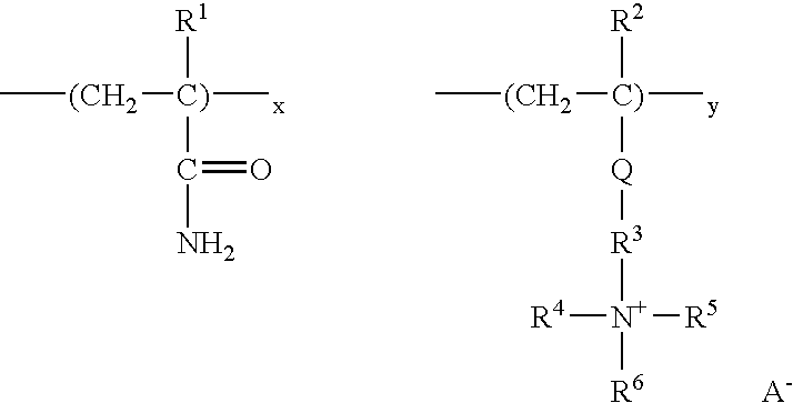
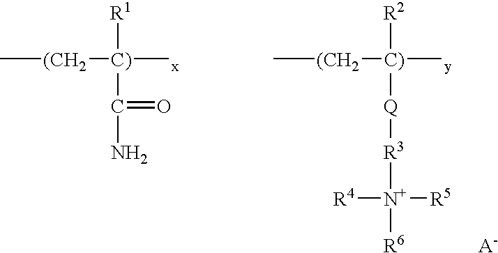
Methods and compositions for improved separation of inverted drilling mud emulsions into their component phases. The emulsion is mixed with a treatment comprising a cationic acrylamide/quaternary ammonium copolymer (I) and a cationic coagulant (II) comprising a copolymer of a tannin, and cationic monomer.

Description

FIELD OF INVENTION [0001] The present invention pertains to methods and compositions for separating drilling mud emulsions into their constituent phases. BACKGROUND OF THE INVENTION [0002] Inverted emulsions (W / O) are those in which a non-oleaginous fluid is present in the dispersed phase and an oleaginous fluid is present as the continuous phase. These emulsions are commonly employed in drilling processes such as for the development of oil, or gas, or sometimes in geothermal and other drilling processes. These inverted emulsions are commonly used to provide stability to the drilled hole, to lubricate the hole, and form a thin filter cake. [0003] Oil based drilling fluids are commonly used in the form of inverted emulsion muds consisting of three phases: an oleaginous phase, a non-oleaginous phase, and a finely divided phase. These fluids also contain a variety of emulsifiers, weighting additives, fluid retention aids, viscosity modifiers, etc., to stabilize the system as a whole an...

Claims


Application Information

Patent Timeline
IPC IPC(8): B01D17/04C09K8/60
CPCB01D17/0217B01D17/047B01D21/0012B01D21/01B01D21/10B03D3/02E21B21/068B03D3/06
Inventor ARCISZEWSKI, JANDUECK, JONATHON
Owner BETZ LAB INC
Why Eureka
Try Eureka