Active seat suspension

a seat suspension and active technology, applied in the direction of shock absorbers, roofs, tractors, etc., can solve the problems of affecting the health of the driver, the vibration of the driver's cab, and the discomfort of exercise of the work, so as to reduce the size of the actuator

Inactive Publication Date: 2006-10-26
BAULTAR I D
View PDF13 Cites 92 Cited by
  • Summary
  • Abstract
  • Description
  • Claims
  • Application Information

AI Technical Summary

Benefits of technology

[0021] More specifically, the object of the present invention is to provide an active suspension for a vehicle driver seat, such for use on a bus, a heavy vehicle or a specialized use vehicle, for example excavating equipment or forestry equipment, in which the operator or the driver is submitted to vibrations, and that comprises an electric actuator allowing to exert a force between the vehicle floor and the seat. The adjustment of the height of the seat is accomplished by an electric actuator or by an independent mechanical system. A controller generates a force command calculated from measur

Problems solved by technology

It is known that irregularities in roads cause the presence of important vibrations in the driver cab for bus drivers or drivers of heavy vehicles such as trucks or specialized use vehicles, for example, excavating or forestry equipment.
Exposures of drivers to these vibrations make the exercise of their work uncomfortable and can have a negative influence on their health.
Therefore, a very soft suspension will allow a considerable reduction in the level of transmitted acceleration, but at the cost of a significant relative displacement.
However, a suspension that is too stiff will maintain a good interaction between the driver and his driving area, but will only offer a weak reduction in the transmitted acceleration.
Back or health problems observed despite the use of this type of suspension demonstrate that passive suspensions do not allow to reach a sufficient level of comfort.
Phase 2: Évaluation de sièges candidats, IRSST, June 1997) demonstrate however that their performance in this use is not appreciably better than the performance of passive suspension having fixed dampening.
These systems have been, in the great majority, put into practice with the help of hydrauli

Method used


Image

  • Active seat suspension
  • Active seat suspension
  • Active seat suspension

Examples


example 1

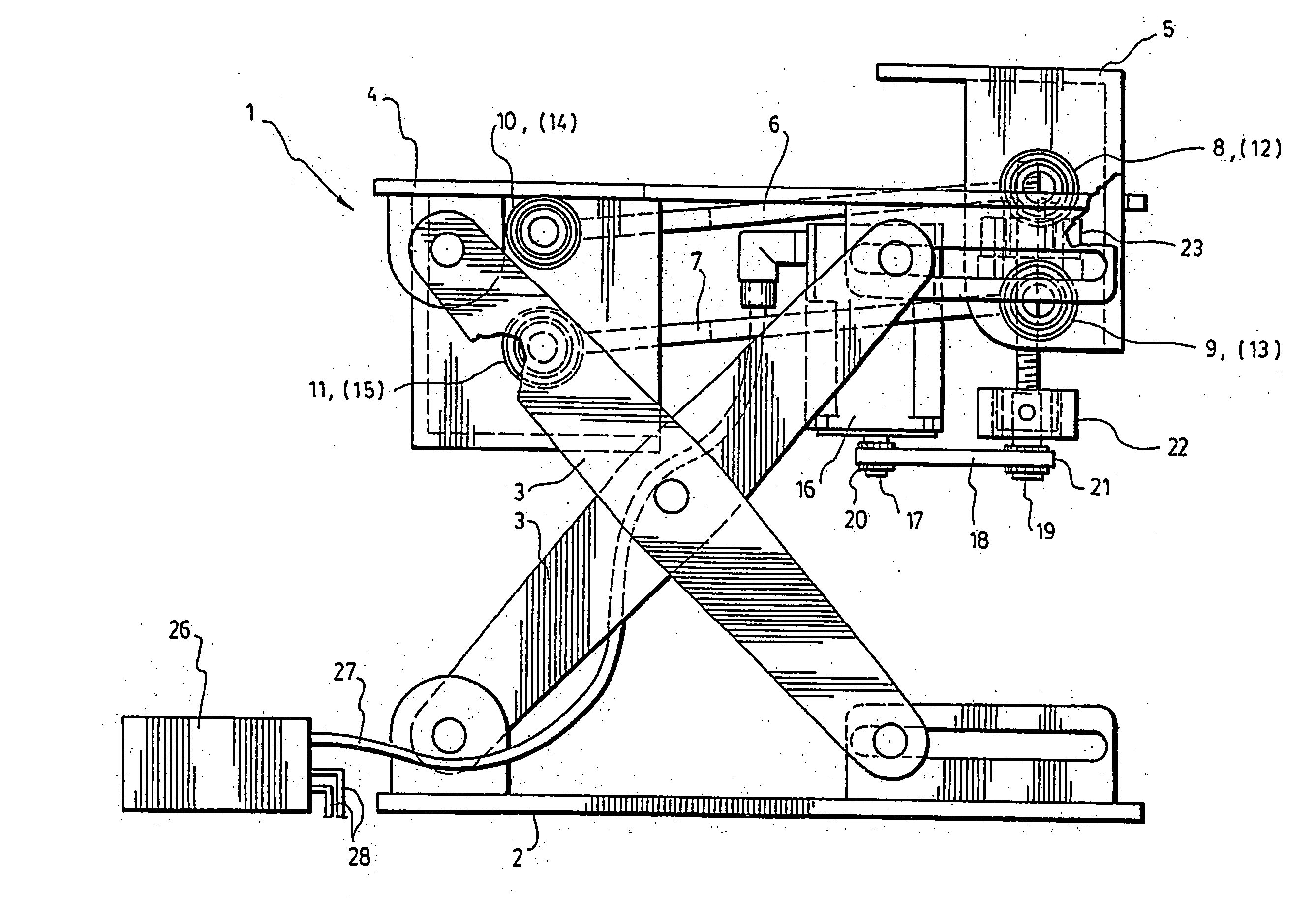
[0058] A possible example of a preferred embodiment of the invention is illustrated in FIGS. 6 to 9 of the appended drawings. In this example, the seat 25 is mounted on an overall system 1 combining the height adjustment and the suspension mechanism.

[0059] Concerning this, one shall note that the height adjustment mechanism is independent of the suspension mechanism. Indeed, the suspension mechanism is “superimposed” on the mechanical system having members or diagonal braces 3 used in the height adjustment mechanism. The height adjustment mechanism also comprises a base 2 fixed to the floor and an element 4 parallel to the base 2. These two elements 2 and 4 are connected between themselves through the cross member or diagonal brace system 3 mentioned above which allows an elevation of the element 4 with respect to the base 2 when it is activated. FIG. 7 shows a high configuration of the system while FIG. 8 shows a low configuration.

[0060]FIG. 7 shows a preferred embodiment of the ...

example 2

[0067] A second example of an embodiment of the invention is illustrated in FIGS. 10 to 12. This example, which is described in the following paragraphs, presents the base of the seat shown in FIGS. 10 and 11 which comprises a guidance mechanism for the suspension superimposed on the height adjustment systems and the forward-backward movement adjustment system for the seat. FIG. 10 shows a seat in a low position, while FIG. 11, shows it in the high position.

[0068] As in the previous example, the height adjustment mechanism is independent of the suspension mechanism. The height adjustment mechanism comprises of a scissor-shaped system having pivotally connecting members 30, 31 and 32. These members are the link between the base 33 and element 34. The adjustment in height that allows an elevation of the element 34 with respect to the base 33, is accomplished through relative displacement of members 30, 31 and 32. The displacement of these members 30, 31 and 32 is controlled by mechan...


PUM


Abstract

An active suspension for a driver seat of a bus or a heavy vehicle which comprises an electric actuator allowing the exertion of the force between the floor of the vehicle and the bottom of the seat. The adjustment of the height of the seat is accomplished by an electric actuator or by an independent mechanical system. A controller generates a control force calculated from measurements obtained by sensors located at different locations on the suspension. Forces exerted by the electric actuator can be relieved by passive element placed in parallel which cannot assume by themselves the role of a suspension for a given application.

Description

INTRODUCTION [0001] The present invention generally relates to an active suspension system for a vehicle driver seat, notably in a buss, a heavy vehicle or a specialized use vehicle, for example, an excavating or forestry equipment, and of which the operator or driver is submitted to vibrations. BACKGROUND OF THE INVENTION [0002] It is known that irregularities in roads cause the presence of important vibrations in the driver cab for bus drivers or drivers of heavy vehicles such as trucks or specialized use vehicles, for example, excavating or forestry equipment. Exposures of drivers to these vibrations make the exercise of their work uncomfortable and can have a negative influence on their health. In order to reduce the acceleration transmitted to the level of the driver's seat, a suspension is often introduced between the vehicle floor and the seat. The seat suspension must minimize the acceleration transmitted to the driver, but must also maintain minimal the gap in position betw...

Claims


Application Information

Patent Timeline
IPC IPC(8): F16F15/00B60N2/02F16M13/00B60N2/50B60N2/52B60N2/54F16F15/023F16F15/027
CPCB60N2/501B60N2/502B60N2/505F16F15/027B60N2/544F16F15/0232B60N2/508
Inventor PAILLARD, BRUNOMAZOYER, JEROMEMASSON, PATRICEBERRY, ALAINALBERT, ANDRE
Owner BAULTAR I D
Why Eureka
Try Eureka