Gas bag module

a technology of gas bags and retaining elements, applied in transportation and packaging, pedestrian/occupant safety arrangements, vehicle safety arrangements, etc., can solve the problems of rapid destruction of retaining elements, etc., and achieve the effect of rapid and risk-free manner

Inactive Publication Date: 2006-10-26
TRW AUTOMOTIVE SAFETY SYST
View PDF17 Cites 10 Cited by
  • Summary
  • Abstract
  • Description
  • Claims
  • Application Information

AI Technical Summary

Benefits of technology

[0009] In preferred embodiments, the retaining element is a meltable catch strap. By using a material that is non-flammable but meltable, it is possible to achieve the at least partial destruction of the retaining element by hot gas in an especially rapid and risk-free manner.
[0010] A gas guiding device can be provided on the second discharge section of the gas generator. This gas guiding device ensures that the escaping hot gas flows in a concentrated manner onto the retaining element and therefore causes an especially rapid destruction of the retaining element.
[0011] Preferably, a second end of the retaining element is attached directly to the second discharge section of the gas generator. In this way, there is no need for a gas guiding device, because the retaining element is impinged by hot gas in any case when the second discharge section has gas flowing through it.

Problems solved by technology

This gas guiding device ensures that the escaping hot gas flows in a concentrated manner onto the retaining element and therefore causes an especially rapid destruction of the retaining element.

Method used


Image

  • Gas bag module
  • Gas bag module
  • Gas bag module

Examples


second embodiment

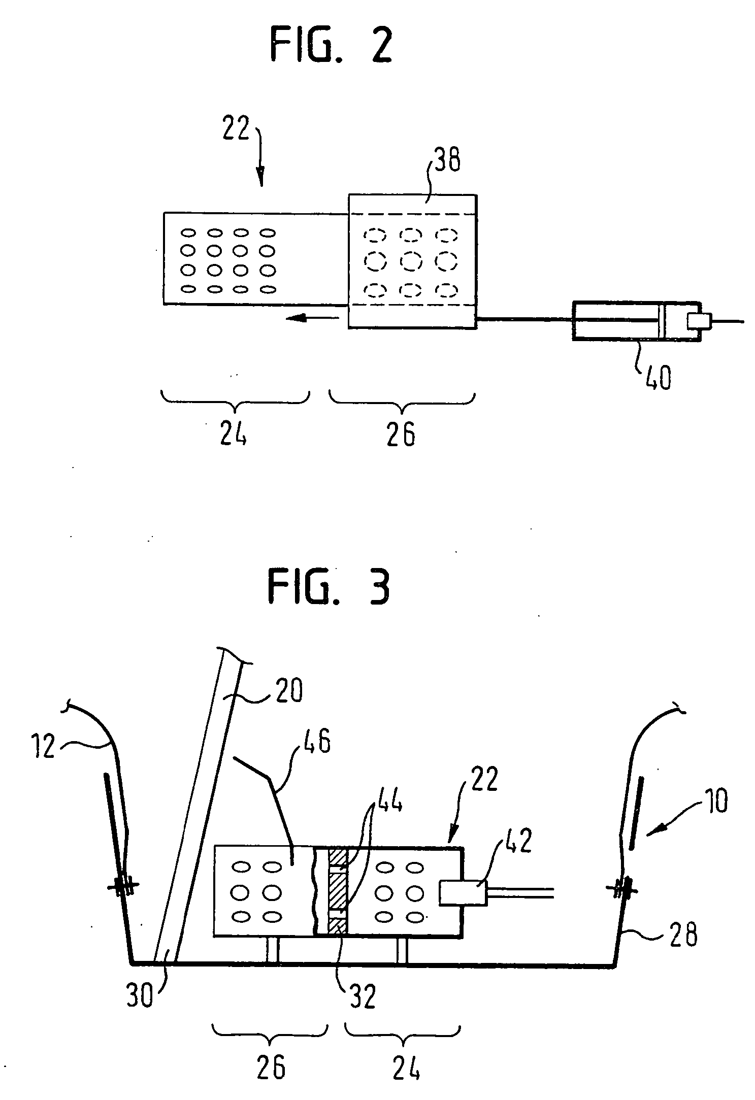
[0026]FIG. 2 shows a gas generator 22 according to the gas bag module. Second discharge section 26 is closed off by a cover 38, which can be moved so that it releases second discharge section 26. First discharge section 24 is not influenced by the motion of cover 38, or it can be closed off completely or partially by cover 38 as a consequence of the motion. In the example shown, cover 38 is a sleeve that surrounds gas generator 22 and that can be moved towards the first discharge section.

[0027] In this embodiment, it is therefore possible to use a cost-effective, single-stage gas generator 22. Nevertheless, a triggering device 40 must be provided, which moves cover 38. Triggering device 40 in this context can be executed so as to be passive or active. A passive triggering device is, for example, a tension band, whose one end is connected to front wall 14 of gas bag 12 and whose second end is connected to cover 38, so that cover 38 is moved as a function of the deployment state of th...

third embodiment

[0028] In the gas bag module according to FIG. 3, gas generator 22 has an ignition device 42, which ignites a first quantity of fuel, which releases the first quantity of gas. A second quantity of fuel for releasing the second quantity of gas is activated by ignition transfer. For this purpose, an ignition transfer device 44 is integrated in wall 32 of gas generator 22. By using a retarder, the ignition transfer process can be timed so that gas bag 12 deploys optimally.

[0029] To ensure that the stream of the second quantity of gas is directed onto retaining element 20, in FIG. 3 a gas guiding device is provided in the form of a sheet metal part 46 on second discharge section 26 of gas generator 22.


PUM


Abstract

A gas bag module (10) includes a gas bag (12), the gas bag having a front wall (14) facing an occupant (16) in an inflated state of said gas bag (12) and being engaged by a first end (18) of a destructible retaining element (20), the retaining element (20) at least partially preventing an unhindered motion of the front wall (14) when the gas bag (12) is inflated. The gas bag module further includes a gas generator (22) for filling the gas bag (12), the gas generator (22) having a first discharge section (24) for a through flow of a first quantity of gas. The gas generator (22) has a separate, second discharge section (26), which can have a second quantity of gas flow through it in a way that is selectively independent of a release of the first quantity of gas or has a time delay with respect to the release of the first quantity of gas, the second quantity of gas being hot gas, which flows to the retaining element (20) through the second discharge section (26) so as to cause a destruction of the retaining element (20).

Description

TECHNICAL FIELD [0001] The invention relates to a gas bag module having a gas bag, the gas bag having a front wall that in the inflated state of the gas bag faces an occupant. A first end of a destructible retaining element engages the front wall, the retaining element at least partially preventing an unhindered movement of the front wall when the gas bag is inflated. In addition, the gas bag module has a gas generator for filling the gas bag, the gas generator having a first discharge section for the through flow of a first quantity of gas. BACKGROUND OF THE INVENTION [0002] Gas bag modules of this type are known from the prior art. They have the advantage that the gas bag, seen from the point of view of the occupant, initially presents a large impact surface instead of great depth. The large impact surface in many seating positions of the occupant assures very good restraint conditions. Moreover, the front wall, which moves towards the occupant, is slowed by the retaining element ...

Claims


Application Information

Patent Timeline
Patent Type & Authority Applications(United States)
IPC IPC(8): B60R21/26B60R21/217B60R21/231B60R21/233B60R21/2338B60R21/2342
CPCB60R21/231B60R21/2338B60R2021/23382B60R21/26B60R21/2342
Inventor FELLHAUER, JOACHIMKEUTZ, MARKUSKREUZER, MARTINLEHMANN, MICHAELMAGOLEY, MARCUSSCHNEIDER, MICHAEL
Owner TRW AUTOMOTIVE SAFETY SYST
Why Eureka
Try Eureka