
Trailing vortex management via boundary layer separation control

a technology of boundary layer separation and trailing vortex, applied in the direction of separation process, air-flow influencer, transportation and packaging, etc., can solve the problem of complex three-dimensional interaction, rapid destruction of trailing vortex coherence in the wake, and generating trailing vortices susceptible to rapid destruction, etc., to achieve high-instable wake structure

Inactive Publication Date: 2005-05-19
NASA
View PDF3 Cites 10 Cited by
  • Summary
  • Abstract
  • Description
  • Claims
  • Application Information

AI Technical Summary

Benefits of technology

[0013] Accordingly, it is an object of the present invention to provide a method and device for modifying wing loading, thereby producing a highly unstable wake structure that leads to rapid destruction of wake vortices. The present invention uses static or dynamic devices to control boundary layer separation, leading to modified wing loading, and in turn producing such a wake structure.
[0014] The invention can be implemented in either a time-invariant or a time-dependent mode. In its time-invariant mode, separation control devices are directly retrofit to the aircraft, resulting in minimal costs. No power is required, since the separated flows that exist over the wing elements are directly exploited by the method. Aircraft aerodynamics are not affected during cruise, because typical low profile vortex generators are tucked away in the cove of the aerodynamic structure. The invention is implemented during landing and take-off, increasing lift and improving aerodynamic quality, with no apparent associated risk. The invention is operable irrespective of weather conditions, and can be applied to high-lift systems found on different aircraft loadings (e.g. fore and aft center of gravity), as well as different airlines.
[0015] In its time-dependent mode, the present invention requires relatively small retrofits to flap elements, for example it may require internally mounted lightweight actuators or externally mounted fliperons. Like the time-invariant mode of the invention, the time-dependent mode of the invention requires low power to operate, since it exploits existing separated flow as a resource, and does not affect aircraft aerodynamics during cruise. Efficiency (L / D) of the aircraft is maintained or increased during landing and take-off with low associated risk. The separation control hardware introduces small perturbations on the span loading, compared to those produced by deflecting control surfaces. Use of the time-dependent mode of the invention allows direct excitation of different wake modes, and can impress large-amplitude forcing of vortex locations while maintaining constant lift and drag. The invention can be applied to different high-lift systems found on different aircraft, and different airlines, and can be used in different weather conditions with or without ground effect.

Problems solved by technology

Separation can be diminished or promoted to vary vortex locations and strengths, so as to generate wake signatures that are unstable, resulting in complex three-dimensional interaction and rapid destruction of vortex coherence in the wake.
For the time-invariant method, separation control is enforced for a significant amount of time, thereby generating trailing vortices that are susceptible to rapid destruction via natural disturbances inherent in the wake or atmosphere.

Method used


Image

  • Trailing vortex management via boundary layer separation control
  • Trailing vortex management via boundary layer separation control
  • Trailing vortex management via boundary layer separation control

Examples


Embodiment Construction

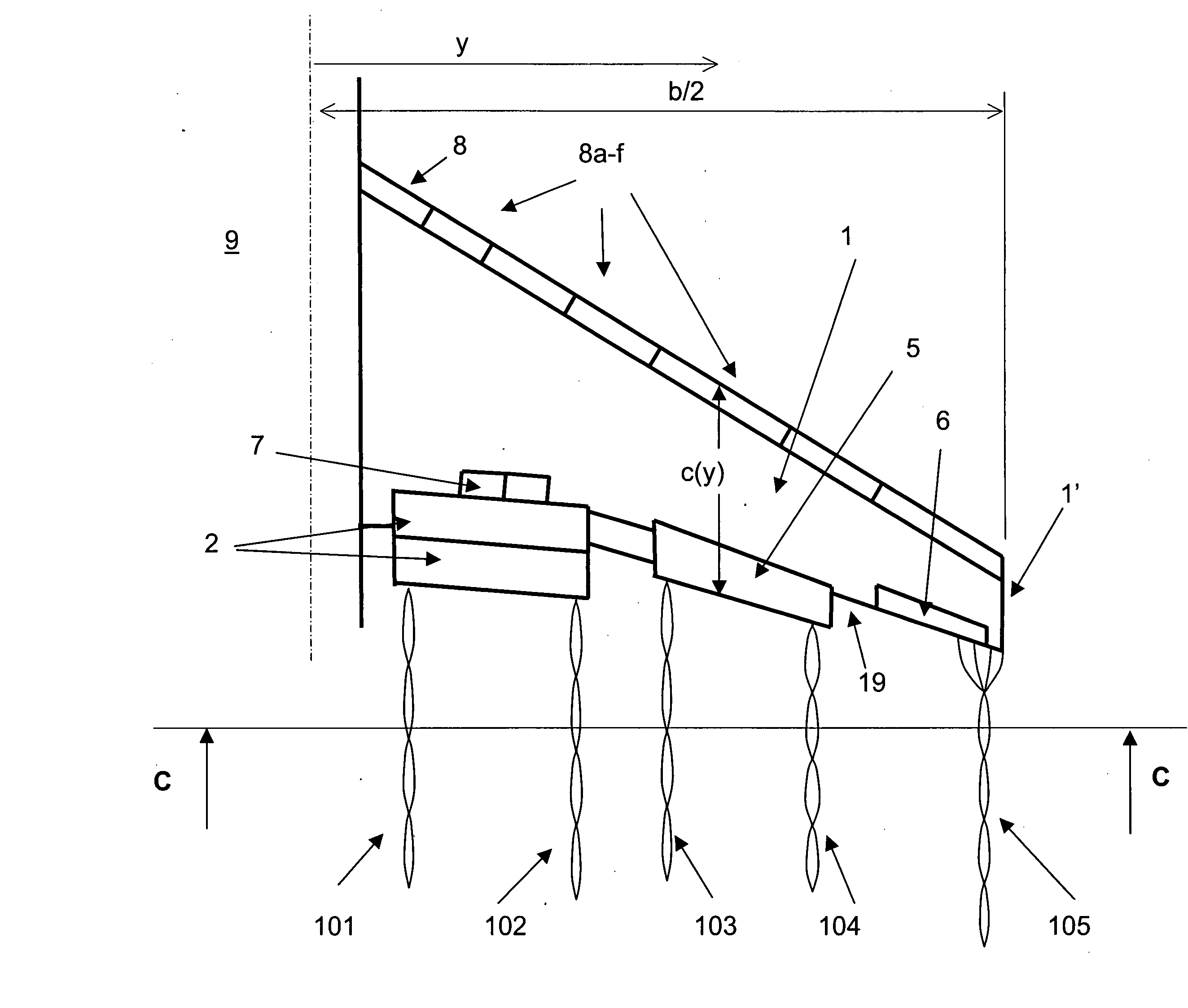
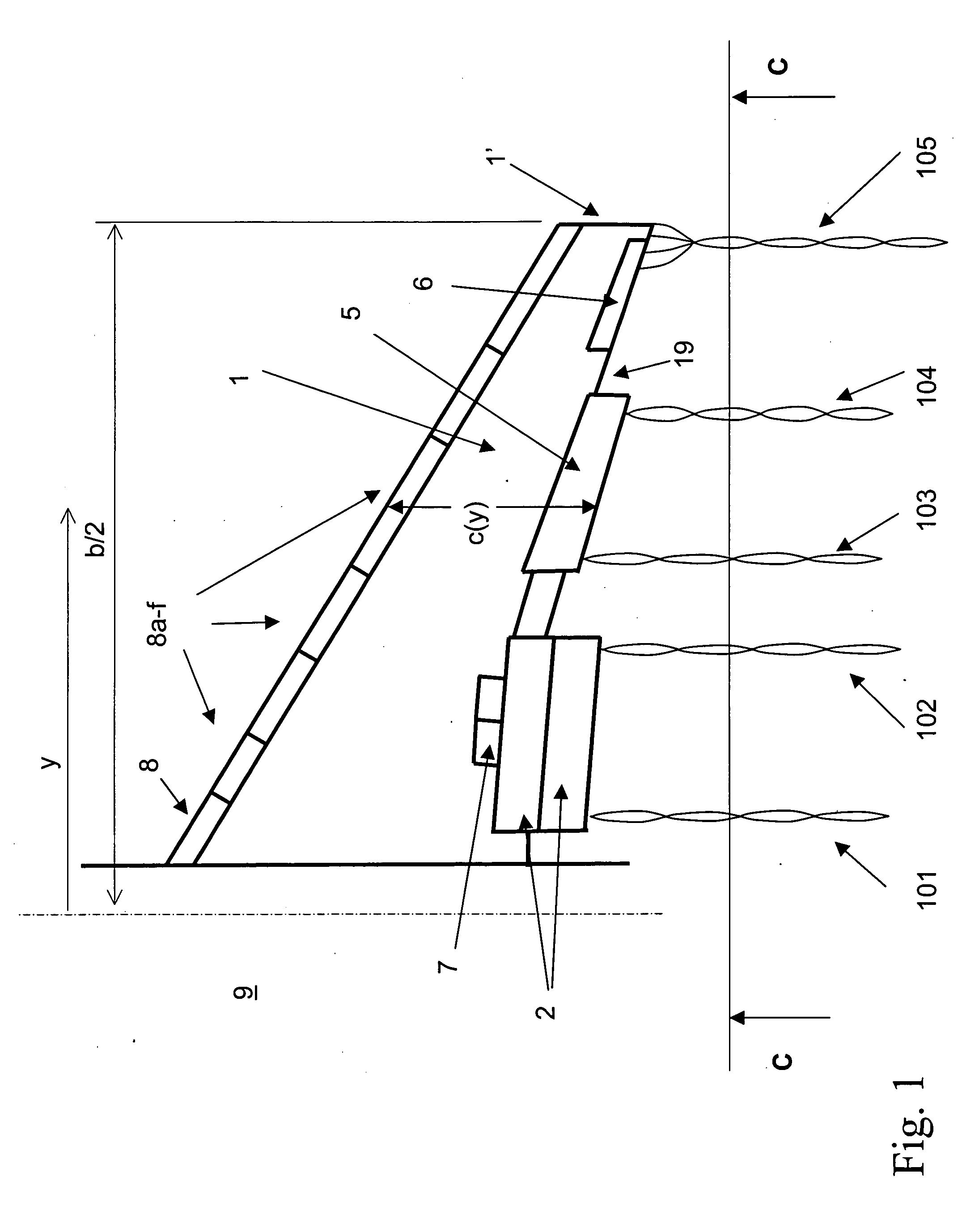
[0052]FIG. 1 depicts a typical starboard airliner wing 1 in planview. The wing includes various control surfaces, some of which serve to control the flight of the aircraft (e.g. aileron 6) and others that are used to generate high-lift for take-off and landing (e.g. inboard flap 2 and outboard flap 5). The wing 1 is attached to a fuselage 9 and in the configuration shown in FIG. 1 has its high-lift system of flaps (2 and 5) deployed. The portside wing is not shown in the figure, and is a mirror image of the starboard wing shown. The spanwise coordinate y is measured from the symmetry plane, i.e. the fuselage center. The two wings have a total wingspan denoted b; thus the starboard wing shown here has a span of b / 2, and the aircraft flies at speed V. In general the lift, l(y), varies along the span y of the wing. The spanwise distance is often expressed in the non-dimensional form y / (b / 2).

[0053] For purposes of clarity, it is important to introduce a number of definitions and termin...


PUM


Abstract

A method and device utilizes boundary layer separation control for the purpose of wake vortex alleviation. Trailing vortices are manipulated by varying the spanwise vortex-sheet strength via either passive or active boundary layer separation control. Boundary layer separation can be diminished or promoted to vary vortex properties, such as locations and strengths, so as to generate wake signatures that are unstable, resulting in complex three-dimensional interaction and rapid destruction of vortex coherence in the wake. Separation control can be achieved in either a time-dependent or a time-invariant mode.

Description

[0001] This application claims the benefit of U.S. Provisional Application No. 60 / 487,478, filed Jul. 11, 2003, and entitled “Vortex Management Via Separation Control.”ORIGIN OF THE INVENTION [0002] The invention described herein was made by an employee of the National Research Council and may be manufactured and used by or for the government for governmental purposes without the payment of royalties thereon or therefor.BACKGROUND OF THE INVENTION [0003] 1. Field of the Invention [0004] The subject invention relates to aerodynamic controls, and relates more specifically to the management of vortices trailing aerodynamic structures. [0005] 2. Description of the Related Art [0006] A well-known problem associated with large aircraft is that of powerful vortices (swirling flows), that trail in their wakes. An aircraft following a leading aircraft in flight may encounter or penetrate the vortices of the leading aircraft and may experience severe upward or downward loads or overpowering r...

Claims


Application Information

Patent Timeline
Patent Type & Authority Applications(United States)
IPC IPC(8): B01DB64C23/04B64C23/06
CPCB64C23/04
Inventor GREENBLATT, DAVID
Owner NASA
Learn More