Shift register and method for driving the same

Active Publication Date: 2006-10-26
LG DISPLAY CO LTD
View PDF9 Cites 60 Cited by
  • Summary
  • Abstract
  • Description
  • Claims
  • Application Information

AI Technical Summary

Benefits of technology

[0028] An object of the present invention is to provide a shift register and a method for driving the same, which transmit at least two independent scan pulses by individual stages, transmit one of the

Problems solved by technology

However, larger LCD area requires longer gate lines.
Unfortunately, longer gate lines are accompanied by higher resistances and capacitances.
Individual scan pulses generated from the stages 100a˜100e are simultaneously applied to the gate line, the next stage, and the previous stage which can result in a serious noise problem in the above-mentioned scan pulses.
In conclusion, the data

Method used


Image

  • Shift register and method for driving the same
  • Shift register and method for driving the same
  • Shift register and method for driving the same

Examples


Embodiment Construction

[0043] Reference will now be made in detail to the preferred embodiments of the present invention, examples of which are illustrated in the accompanying drawings. Wherever possible, the same reference numbers will be used throughout the drawings to refer to the same or like parts.

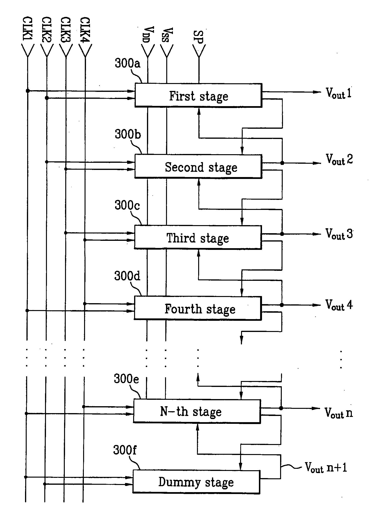
[0044]FIG. 3 is a circuit diagram illustrating a shift register according to an embodiment of the present invention. As illustrated, the shift register includes N stages 300a˜300e serially connected to each other, and a single dummy stage 300f. In this instance, each of the individual stages 300a˜300e outputs at least two independent scan pulses. One of the two scan pulses is applied to both a gate line of a corresponding stage of a liquid crystal panel (not shown) and a previous stage, and the other one is applied to the next stage. However, it should be noted that more than two independent scan pulses may be outputted by each stage.

[0045] The scan pulses independently generated from individual stages 30...


PUM


Abstract

A shift register and a method for driving the same are disclosed. The shift register includes a plurality of stages serially connected to each other. Each of the stages independently generates first and second scan pulses. The first scan pulse is simultaneously applied to a previous stage and to a corresponding gate line of a liquid crystal panel. The second scan pulse is applied to a next stage. The shift register prevents scan pulses applied to each stage from being distorted, and prevents a multi-output signal from being generated.

Description

[0001] This application claims the benefit of the Korean Patent Application No. 10-2005-0033589, filed on Apr. 22, 2005, which is hereby incorporated by reference as if fully set forth herein. BACKGROUND OF THE INVENTION [0002] 1. Field of the Invention [0003] The present invention relates to a shift register, and more particularly, to a shift register that includes a plurality of stages where each stage supplies a scan pulse to the next stage and independently to a gate line and thus, preventing the scan pulse applied to the next stage from being distorted, and a method for driving the same. [0004] 2. Discussion of the Related Art [0005] Generally, a Liquid Crystal Display (LCD) includes a liquid crystal panel in which a plurality of pixel areas are arranged in the form of a matrix and a drive circuit for driving the liquid crystal panel. A desired image is displayed by controlling an optical transmission rate of the liquid crystal in the liquid crystal panel by using electric fiel...

Claims


Application Information

Patent Timeline
IPC IPC(8): G09G3/36
CPCG09G3/3677G11C19/28G09G2320/0223E04H15/34E04H15/60
Inventor JANG, YOUNG HOKIM, BINN
Owner LG DISPLAY CO LTD
Why Eureka
Try Eureka