Image synthesis method, image synthesis apparatus, and storage medium

a technology of image synthesis and image synthesis, which is applied in the field of image synthesis method, image synthesis apparatus, and storage medium, can solve the problems of heavy computational burden on the apparatus, user's failure to select the appropriate mapping mode, and serious apparatus failure, and achieves the effects of reducing processing time, enhancing quality, and quick reading

Inactive Publication Date: 2006-10-26
CANON KK
View PDF19 Cites 53 Cited by
  • Summary
  • Abstract
  • Description
  • Claims
  • Application Information

AI Technical Summary

Benefits of technology

[0011] Another object of the present invention is to provide an image synthesis method, an image synthesis apparatus, and a storage medium in which a mapping mode is easily set when synthesizing an image.
[0031] As described above, an appropriate mapping mode can be easily set. A panoramic synthesis image is obtained without special knowledge. The mapping mode can be selected in a more accurate manner. A user can intentionally select a different mapping mode. Hence, flexibility is provided in selecting the mapping mode. When the user inappropriately changes the mapping mode, the user is warned of the incorrect operation and obtains the synthesized image. It is possible to cut a region without a margin, and that region can be printed or stored. A synthesized image can be generated in any mapping mode by using common coordinate-space transformation parameters and performing processing in accordance with the mapping mode. Because computation of the coordinate-space transformation parameters is omitted when the mapping mode is changed, the processing time is substantially decreased when the mapping mode is changed. It is possible to generate a synthesized image of enhanced quality because the synthesized image need not be transformed again. The user is enabled to set a reference position at a desired position when generating a synthesized image. This flexibly implements geometric correction, such as tilting and shifting correction. By reading a number of synthesized images and coordinate-space transformation parameters generated by changing the mapping mode or setting the reference position, a synthesis result can be obtained at an arbitrary point. The previously-generated images are quickly read, thereby improving efficiency in the editing operation.

Problems solved by technology

When a synthesized image is formed on a region in which the horizontal viewing angle is 180° or greater in the planar mapping mode, the synthesized image cannot be mapped on a single plane, possibly causing a serious apparatus failure.
When the user is not knowledgeable about these mapping modes, the user may fail to select the appropriate mapping mode.
This places a heavy computational burden on the apparatus, requires a long processing time, and is extremely inefficient.

Method used


Image

  • Image synthesis method, image synthesis apparatus, and storage medium
  • Image synthesis method, image synthesis apparatus, and storage medium
  • Image synthesis method, image synthesis apparatus, and storage medium

Examples


first embodiment

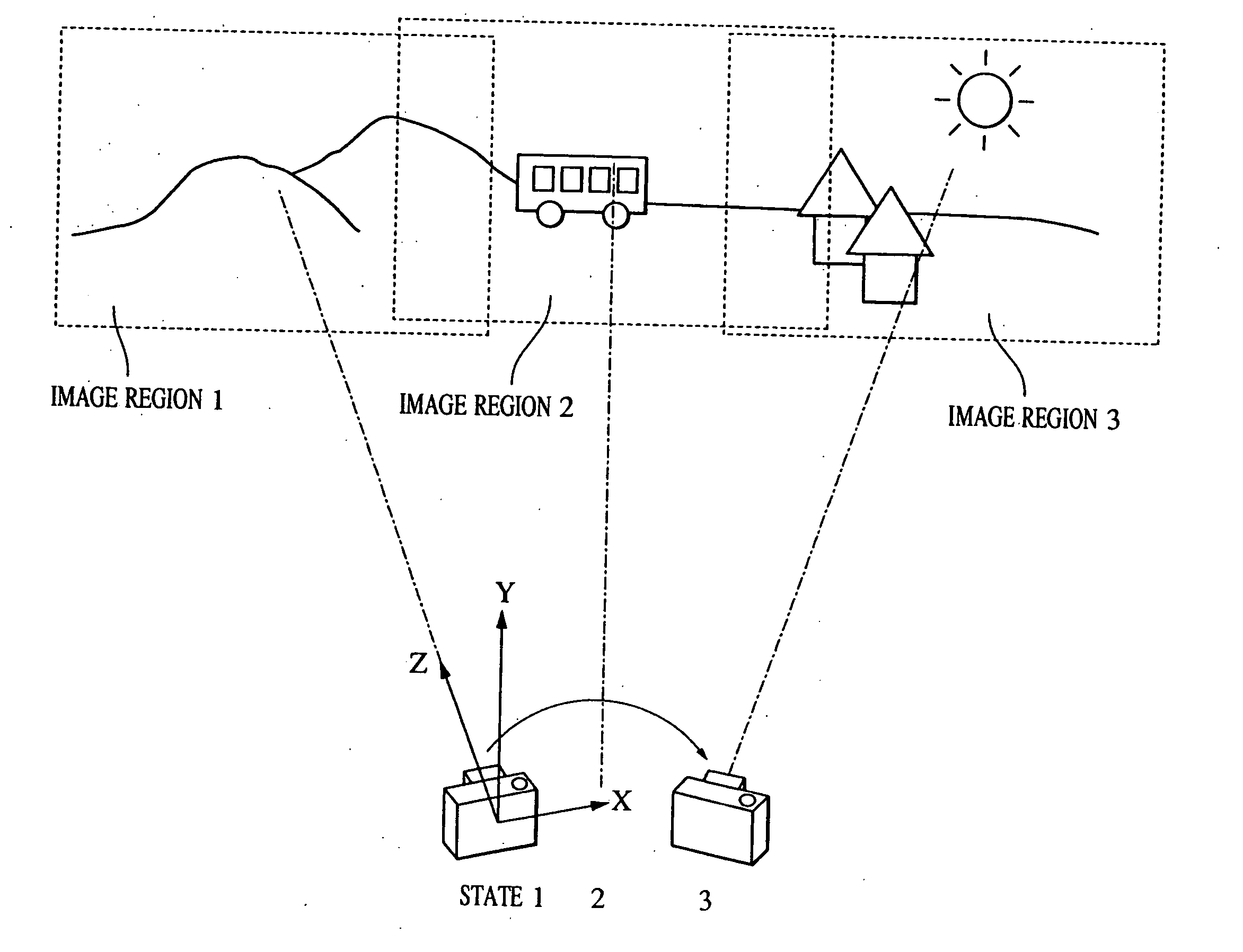
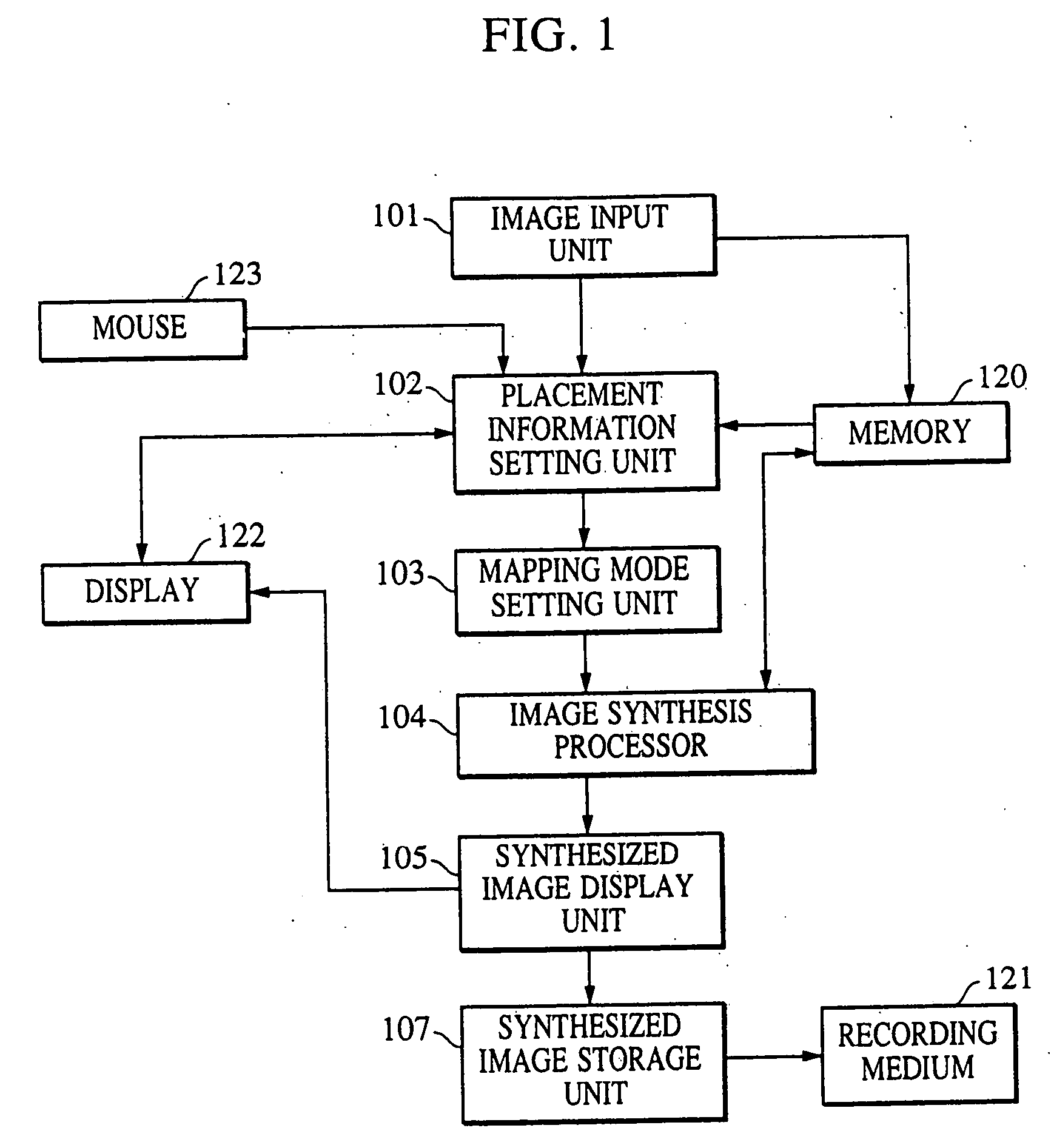
[0063]FIG. 1 schematically shows a panoramic image synthesis method and apparatus according to the present invention. Referring to FIG. 1, an image input unit 101 inputs a plurality of images to be used for image synthesis. A placement information setting unit 102 sets the placement relationship among the input images. A mapping mode setting unit 103 automatically sets a mapping mode for synthesizing an image based on the information from the placement information setting unit 102. An image synthesis processor 104 generates synthesis parameters among the images and generates a synthesized image. A synthesized image display unit 105 displays the synthesized image formed by combining the images based on the synthesis parameters. A synthesized image storage unit 107 stores the resultant synthesized image in a recording medium 121 or the like.

[0064] The image input unit 101 inputs a plurality of images. The images can be input by reading images recorded in a recording medium, such as a ...

third embodiment

[0107] A panoramic image synthesis method and apparatus according to the present invention restrict the number of mapping modes to be selected to two, i.e., the planar mapping mode and the vertical-cylinder mapping mode. The restriction on the types of mapping modes reduces the processing load.

[0108]FIG. 17 shows the panoramic image synthesis method and apparatus of the third embodiment. Since the available types of mapping modes are limited to the planar mapping mode and the vertical-cylinder mapping mode in the third embodiment, a mapping mode setting unit 130 differs from those in the other embodiments. The operation of the mapping mode setting unit 130 is described.

[0109] The mapping mode setting unit 130 computes the number of images in the horizontal direction and the vertical direction based on placement information set by a placement information setting unit 102. When there are m number of images in the horizontal direction and n number of images in the vertical direction, ...

second embodiment

[0110] When the vertical-cylinder mapping mode is selected, it performs the coordinate transformation in the vertical direction in the same manner as the planar mapping mode. The larger the viewing angle of the synthesized image in the vertical direction, the more the peripheral portion becomes deteriorated, failing to generate a satisfactory image. To avoid this, as described in the second embodiment, the reference values of the displayable viewing angle are set in advance, and the synthesized image within these reference values is generated.

[0111] In the above example, only the placement information is used to set the mapping mode. Alternatively, it is possible to obtain focal length f using an obtaining unit (not shown). When m≦Tm, n≦Tn, and f≧Tf, the planar mapping mode is set. Otherwise, the vertical-cylinder mapping mode is set.

[0112] Although a combination of the planar mapping mode and the vertical-cylinder mapping mode is used in this example, the combination can be formed...


PUM


Abstract

An image synthesis method includes a placement information obtaining step of obtaining placement information about a plurality of images in which adjacent images have a common subject region, and a synthesis step of combining the images using a mapping mode in accordance with the placement information. Prior to performing mapping transformation of the input images, coordinate-space transformation parameters for transforming the coordinate space of one image among the images into the coordinate space of another image are generated. The images are combined based on a given mapping mode and the coordinate-space transformation parameters.

Description

BACKGROUND OF THE INVENTION [0001] 1. Field of the Invention [0002] The present invention relates to technology for combining a plurality of images in which adjacent images have a common subject region and generating a synthesized image. [0003] 2. Description of the Related Art [0004] Hitherto, the synthesis of a panoramic image by combining a plurality of images is performed by a conventional method of capturing images of a subject in a plurality of regions and synthesizing a single image using image information about a common subject region, as shown in FIG. 10. FIG. 11 shows a sectional view taken through the XZ plane of FIG. 10. As shown in FIG. 11, an image synthesis method includes a mode (planar mapping mode) of mapping captured images onto a single plane 800 and synthesizing an image or a mode (cylinder mapping mode) of mapping the images onto a virtual cylindrical surface 801 having a radius f and synthesizing an image. FIG. 12 schematically shows a synthesized image obtain...

Claims


Application Information

Patent Timeline
Patent Type & Authority Applications(United States)
IPC IPC(8): G06T15/20
CPCG06T3/4038
Inventor KATAYAMA, TATSUSHITAKIQUCHI, HIDEOYANO, KOTAROHATORI, KENJI
Owner CANON KK
Why Eureka
Try Eureka