
Synchronizing method in optical access network, optical switching device, center device, and remote device

a technology of optical access network and synchronizing method, which is applied in the direction of data switching network, multiplex communication, star/tree network, etc., can solve the problem of not being able to give the medium of obtaining tz, and achieve the effect of reducing the cost of invention

Active Publication Date: 2006-10-26
NEC COMM SYST
View PDF3 Cites 22 Cited by
  • Summary
  • Abstract
  • Description
  • Claims
  • Application Information

AI Technical Summary

Benefits of technology

[0035] According to the invention claimed in claim 2, the identification number ID of the remote device to which the control packet is transmitted and the transmission request R of the upstream control packet are used with the result that the start time of the upstream optical switching element of the optical switching device can be accurately given while the ranging can be performed.
[0088] In accordance with the present invention, the optical switching device is provided with a ranging function, and the center device performs ranging of the optical switching device in the same manner as the ranging of the remote devices. The center device transmits to the optical device a difference between the two round trip times which is a ranging result thereof: the round trip time between the center device and the remote device and the round trip time between the center device and the optical switching device thereby enabling obtaining the connection start time of the upstream optical switching element by calculating the connection start time using the difference thereof.

Problems solved by technology

However, generally, distance between the ONU and OLT, and distance between the ONU and the OSM are arbitrary, and medium for obtaining Tz cannot be given.
Problem is how to obtain this Tz in the OSM.

Method used


Image

  • Synchronizing method in optical access network, optical switching device, center device, and remote device
  • Synchronizing method in optical access network, optical switching device, center device, and remote device
  • Synchronizing method in optical access network, optical switching device, center device, and remote device

Examples


embodiment 1

(Method 1)

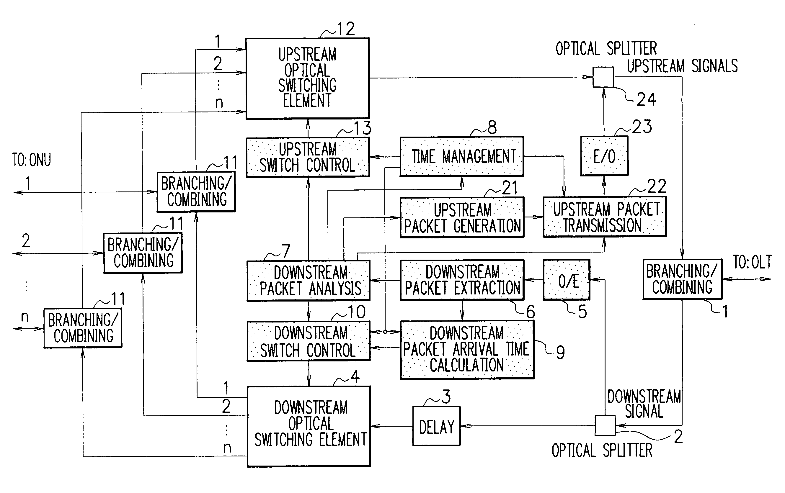
[0189] In Embodiment 1, OLT carries out ranging to OSM, too, RTTs denotes the round-trip delay time of OLT and OSM, TZ=RTTa—RTTs from the round trip time RTTa of OLT and ONU is acquired from OLT, and using this Tz, the connection start time of the upstream optical switching element is determined.

[0190]FIG. 1 describes the present embodiment.

[0191] The present embodiment is characterized in that OLT carries out ranging against OSM and round-trip time RTTs is measured as is the case in that OLT carries out ranging for ONU and round-trip time RTTa of the control packet is measured.

[0192] As shown in the figure, in order for OSM to use the delay time Tz=RTTa−RTTs, OLT informs RTTa and RTTs or its difference RTTa−RTTs information, OLT transmits the information of RTTa, RTTs or their difference RTTa−RTTs to OSM. Once OSM acquires Tz, the connection start time t3* of the upstream optical switching element can be obtained as t3*=t2+tz−Ty1. However, Ty1 is the delay time from ...

embodiment 2

(Method 2)

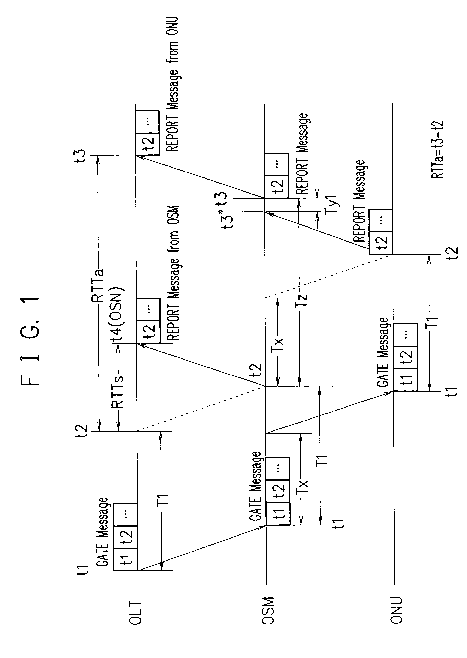
[0193] When OLT carries out the first ranging of ONU, the arrival time t3 of the REPORT message (upstream control packet) to the GAT message (downstream control packet) is found at the outgoing port of the upstream optical switching element of the optical switch module, Tz(=t3−t2) is found from the grant start time t2 written in the GATE message, and using this Tz, the contact start time of the upstream optical switching element is determined.

[0194]FIG. 2 describes embodiment 2.

[0195] In OSM, first of all, LLID, t1, and t2 obtained from the GATE message in the ONU direction are used. The OSM clock is set to time t1 when the GATE message is received.

[0196] First of all, the distance between OSM and ONU is optional and time t2+Tx is designated as the contact start time of the upstream switching element by a clock of OSM which detects the arrival of the REPORT message at the outgoing port of the optical switch module and the contact duration time is set to Tw, the rangin...

embodiment 3

Method 3

[0198] At the incoming port of the upstream optical switching element in OSM, the upstream packet corresponding to the GATE message is detected at LLID, Tz=t3*−t2 is found from the arrival time t3* by the upstream packet and using this Tz, the contact start time of the upstream optical switching element is determined. However, t2 is the grant start time of ONU written in the GATE message.

[0199]FIG. 3 describes the present embodiment.

[0200] The present embodiment enables the detection of the arrival time t3* of the upstream control packet at the incoming port of the upstream switch, enables grasping of the correspondence with the GATE message from LLID of the upstream packet, and enables the evaluation of delay time Tz*=t3*−t2 from the time stamp of the GATE message. After this Tz* is obtained, the arrival time t3* of the upstream control packet, that is, the contact start time t3* of the upstream optical switch can be obtained at t3*=Tz*+t2.


PUM


Abstract

To provide synchronizing methods, optical switch modules, center devices, remote devices, optical access systems, optical access networks, programs, and recording media in the optical access network which can give the connection start time of the upstream optical switching element of the optical switch module. To the optical switch module, ranging functions are provided and the center device OLU carries out ranging of the optical switch module OSM as is the case of ranging of the remote device ONU. The center device OLU transmits the difference between roundtrip time of the remote device ONU and roundtrip time of optical switch module OSM, which is the result of these rangings, to the optical switch module OSM, and the optical switch module OSM can obtain the contact start time of the upstream optical switching element by calculating the contact start time using the difference.

Description

BACKGROUND OF THE INVENTION [0001] 1. Field of the Invention [0002] The present invention relates to a synchronizing method in an optical access network, an optical switching device, a center device, and a remote device. [0003] 2. Related Art [0004] Proposed is PON (Passive Optical Network) of an optical access network without using OSM (Optical Switching device) (for example, referring to non-patent document 1). The PON is configured with a passive element being at least one optical splitter between a center (OLT) and a remote device (ONU) with a tree shape. The PON uses the passive element, however the PON does not use the optical switching device. [0005] The technique described in the non-patent document 1 determines a relationship between a time and a period, namely the synchronizing method, between two devices of the OLT and ONU, which constitutes the PON. [0006] Here, there is described the relationship between the center device (OLT) in cases where there is no optical switchi...

Claims


Application Information

Patent Timeline
IPC IPC(8): H04L12/56H04B10/27H04B10/272H04B10/524H04J14/00H04J14/02H04L12/44
CPCH04J3/0682H04L7/0075H04Q2011/0064H04Q2011/0045H04Q11/0067
Inventor NOMURA, TAKUMIUEDA, HIROMIMAKINO, KUNITETSUKASAI, HIROYUKITSUBOI, TOSHINORIKUROKAWA, HIROAKIKOBAYASHI, HIROKAZUENDO, HIROYUKI
Owner NEC COMM SYST
Learn More