Scheme for operating a wireless station having directional antennas

a wireless station and directional antenna technology, applied in the field of wireless networking, can solve the problems of deafness, interference between transmissions, and original 802.11 protocol not designed for directional antennas, and achieve the effects of enhancing hidden station problems and deafness problems, and solving the problem of enhanced deafness

Inactive Publication Date: 2006-10-26
FUJITSU LTD
View PDF6 Cites 44 Cited by
  • Summary
  • Abstract
  • Description
  • Claims
  • Application Information

AI Technical Summary

Benefits of technology

[0055] The many features and advantages of the invention are apparent from this detailed specification and, thus, it is intended by the appended claims to cover all such features and advantages of the invention that fall within the true spirit and scope of the invention. Further, since numerous modifications and changes will readily occur to those skilled in the art, it is not desired to limit the invention to the exact construction and operation illustrated and described, and accordingly all suitable modifications and equivalents may be resorted to, falling within the scope of the invention. Additionally this application incorporates by reference the paper “Enhancing 802.11 Wireless Networks with Directional Antenna and Multiple Receivers” by Chenxi Zhu, Tamer Nadeem, and Jonathan Agre, Fujitsu Laboratories of America, Technical Memorandum No: FLA-PCR-TM-21.

Problems solved by technology

A consequence of increasing deployment of wireless networks, coupled with limited number of channels and unlicensed spectrum usage, is that the interference between transmissions is becoming a serious problem.
However, the original 802.11 protocol was not designed for directional antennas.
When directional antennas are used, new problems such as the enhanced hidden station problem and the deafness problem, arise.
They increase the likelihood of collisions.

Method used


Image

  • Scheme for operating a wireless station having directional antennas
  • Scheme for operating a wireless station having directional antennas
  • Scheme for operating a wireless station having directional antennas

Examples


Embodiment Construction

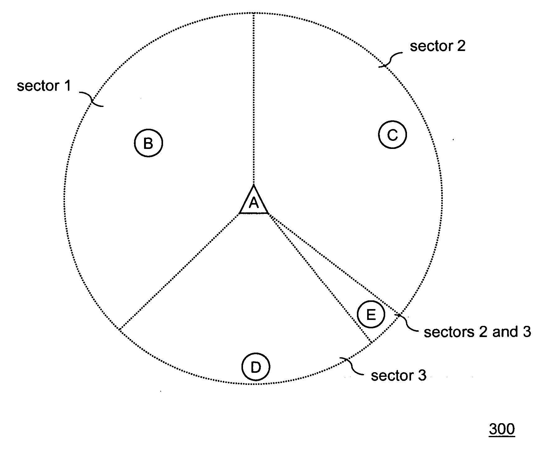
[0022] The present invention is a new scheme called sectorized MAC (“S-MAC”), which uses multiple directional antennas and multiple receivers to provide 360 degree coverage around a station. The scheme allows a station transmitting in some sectors to receive in others. It addresses the hidden station problem and the deafness problem by continuously monitoring the channel in all directions at all time for remote stations. The S-MAC protocol lends itself to both ad hoc mode and infrastructure mode, and can readily inter-operate with stations using an omni antenna. In fact, the sectorized operation of S-MAC is transparent to a regular omni station. A regular station can operate with the belief that all stations are omni and operate with the standard 802.11 MAC.

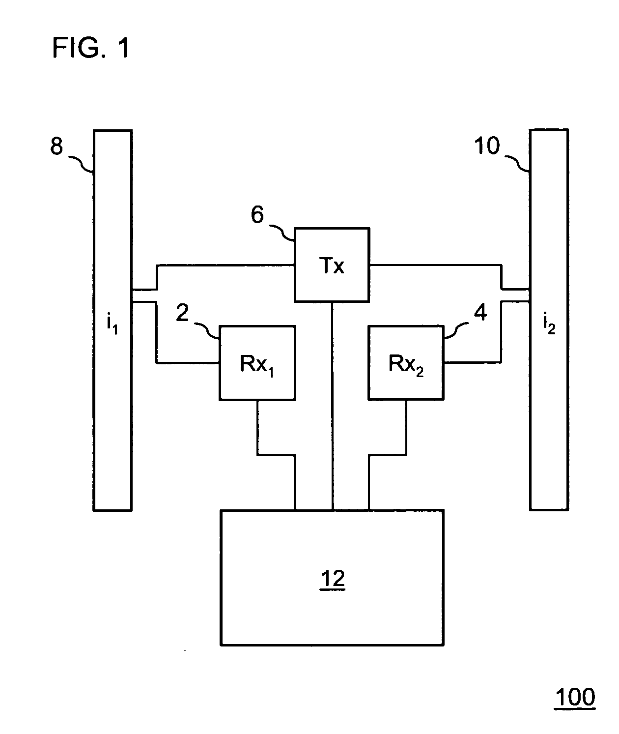
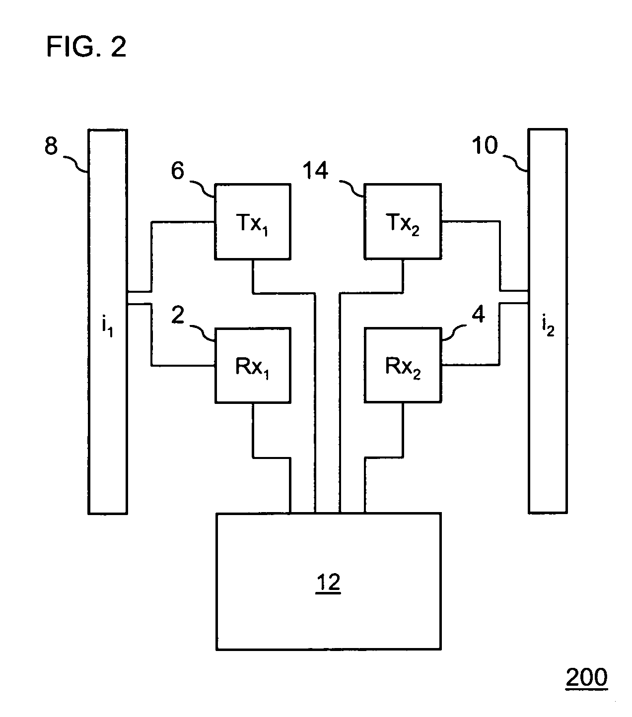
[0023] The coverage area of an S-MAC station is divided into M antennas, with directional antennas i1 through iM corresponding to each sector. The sectors could overlap due to antenna side lobes and back lobes. The station is eq...


PUM


Abstract

Disclosed is a wireless station having a receiver and a network allocation vector associated with each of a plurality of directional antennas. The receivers concurrently listen for frames from remote stations. When any receiver detects a frame from a remote station, the receiver activates its associated NAV. The station has one or more transmitters that can transmit using the antennas. While transmitting a signal using an antenna, the receivers associated with any non-transmitting antennas continue to listen for signals from remote stations. The station cancels any signals from the transmitting antenna received by the non-transmitting antennas. To perform the cancellation, the station performs a self-calibration procedure. The station can self-calibrate by either silencing neighboring stations or by inserting null tones into a transmitted calibration signal.

Description

CROSS-REFERENCE TO RELATED APPLICATIONS [0001] This application is related to and claims priority to U.S. Provisional Application No. 60 / 669,381, filed Apr. 8, 2005, in the U.S. Patent and Trademark Office, the contents of which are incorporated herein by reference.BACKGROUND OF THE INVENTION [0002] 1. Field of the Invention [0003] The present invention is directed to wireless networking. Specifically, the invention pertains to a method of operating a wireless station using directional antennas. [0004] 2. Description of the Related Art [0005] Wireless networks have enjoyed tremendous popularity in recent years. A consequence of increasing deployment of wireless networks, coupled with limited number of channels and unlicensed spectrum usage, is that the interference between transmissions is becoming a serious problem. [0006] Using directional (or sectorized) antennas is a method to reduce the interference and to increase the range and the capacity for wireless networks. In general, n...

Claims


Application Information

Patent Timeline
Patent Type & Authority Applications(United States)
IPC IPC(8): H04B1/00H04B15/00
CPCH04W16/28H04W84/12H04W74/0808
Inventor ZHU, CHENXINADEEM, TAMERAGRE, JONATHAN
Owner FUJITSU LTD
Why Eureka
Try Eureka