Ultrasonic diagnostic equipment and method of controlling the same

a technology of ultrasonic diagnostic equipment and control equipment, applied in diagnostics, medical science, instruments, etc., can solve the problems of large displacement of individual parts, motion artifacts on images, and the fundamental wave remains unabated, and achieve the effect of enhancing the visibility of puncture needles

Inactive Publication Date: 2006-10-26
KK TOSHIBA +1
View PDF11 Cites 41 Cited by
  • Summary
  • Abstract
  • Description
  • Claims
  • Application Information

AI Technical Summary

Benefits of technology

[0013] The present invention has been made in view of the above circumstances, and it has for its object to provide an ultrasonic diagnostic equipment which has a function

Problems solved by technology

Accordingly, when the method is applied to the actual living body in which the motions of organs represented by the heart exist, displacements occur at the individual parts between the reception signals of 2 rates under the influence of the motions, with the result that the fundamental wave remains unerased and gives rise to motion artifacts on an image.
Besides, when the interval of the transmissions of the ultrasonic pulses, namely, a PRF (Pulse Reputaion Frequency: pulse repetition fr

Method used


Image

  • Ultrasonic diagnostic equipment and method of controlling the same
  • Ultrasonic diagnostic equipment and method of controlling the same
  • Ultrasonic diagnostic equipment and method of controlling the same

Examples


first embodiment

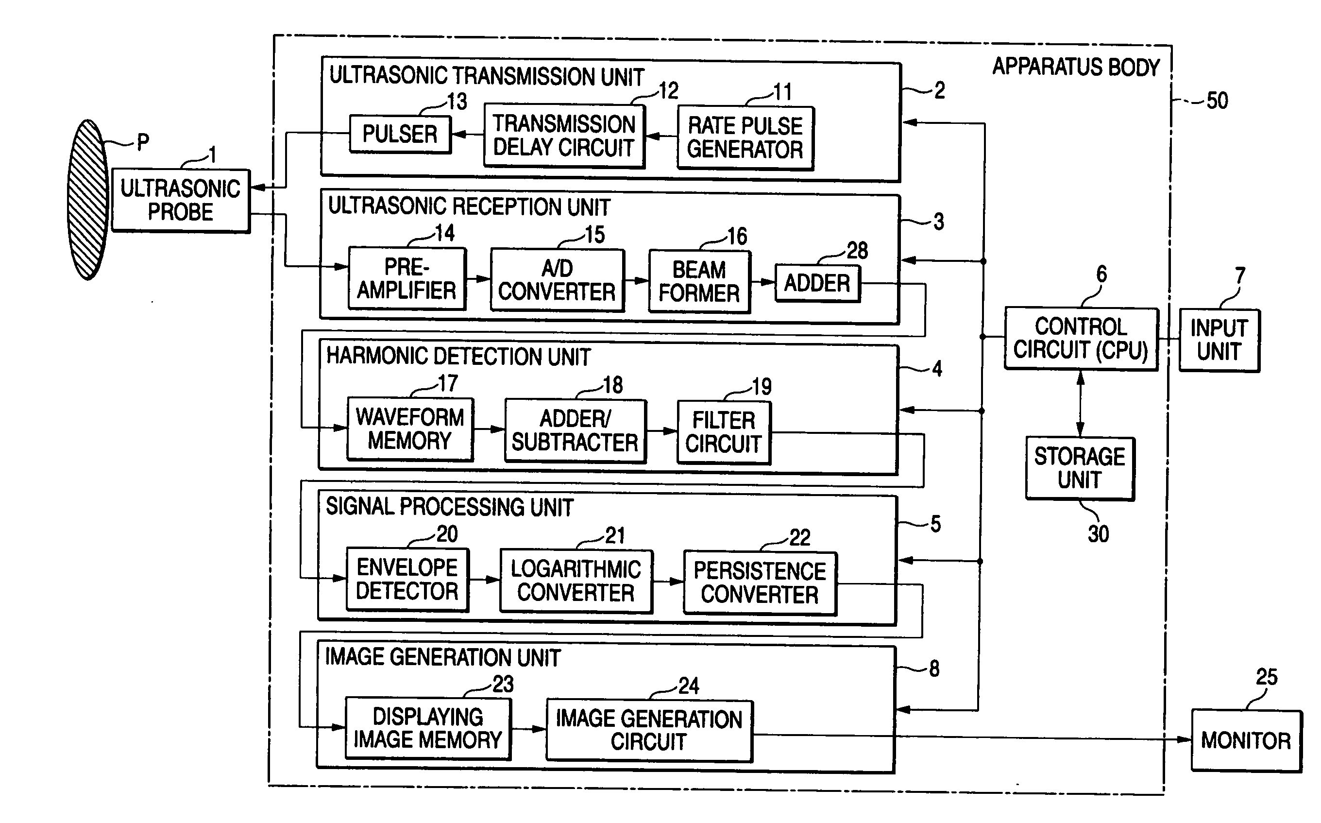
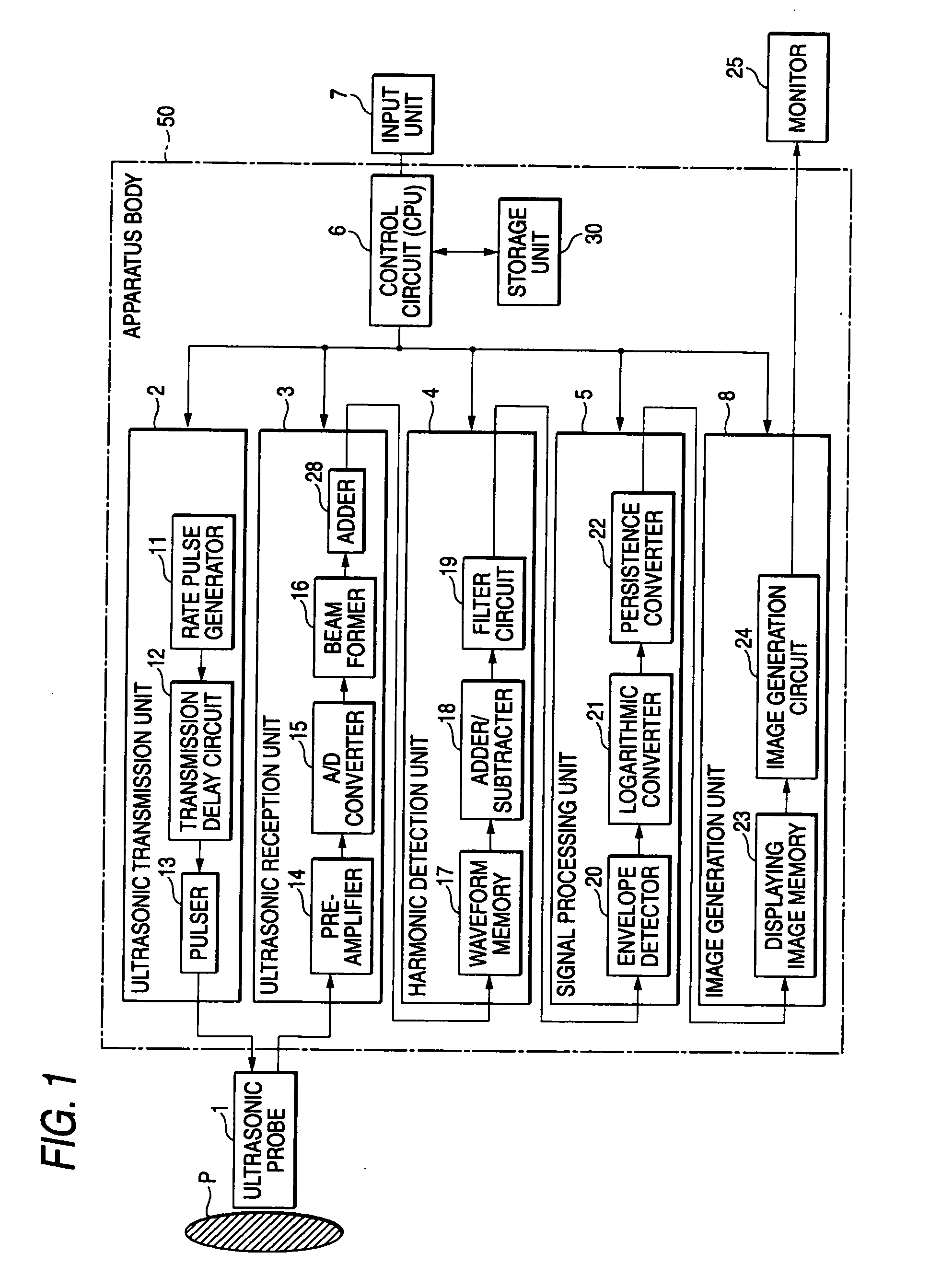
[0041]FIG. 1 shows a block configuration diagram of an ultrasonic diagnostic equipment according to this embodiment. As shown in the figure, the ultrasonic diagnostic equipment is configured of an ultrasonic probe 1, a storage unit 30, an input unit 7, a monitor 25 and an apparatus body 50.

[0042] The ultrasonic probe 1 generates ultrasonic waves and transmits them to a patient, and it receives reflection waves reflected from within the patient and generates echo signals. It has piezoelectric transducers which are acoustoelectric reversible transducers of piezoelectric ceramics or the like. The plurality of piezoelectric transducers are arrayed in parallel, and are disposed at the distal end of the ultrasonic probe 1.

[0043] The storage unit 30 stores therein images formed in the past, images accepted into the equipment from a network or a detachable type storage medium, dedicated programs for executing predetermined imaging sequences, and so forth.

[0044] The input unit 7 includes ...

second embodiment

[0075] Next, the second embodiment of the invention will be described. This embodiment consists in that imaging which enhances the visibilities of a puncture needle, etc. is performed by further utilizing a rate subtraction method. Incidentally, the “rate subtraction method” is a technique which performs the imaging by utilizing the difference between inphase images (images in the same polarity), and which is stated in, for example, JP-A-8-336527.

[0076]FIG. 7 is a conceptual diagram for explaining a scan sequence which is executed by a puncture mode function according to the second embodiment. Besides, FIG. 8 is a conceptual diagram for explaining the signal processing of ultrasonic echo signals as is executed by the puncture mode function according to the second embodiment.

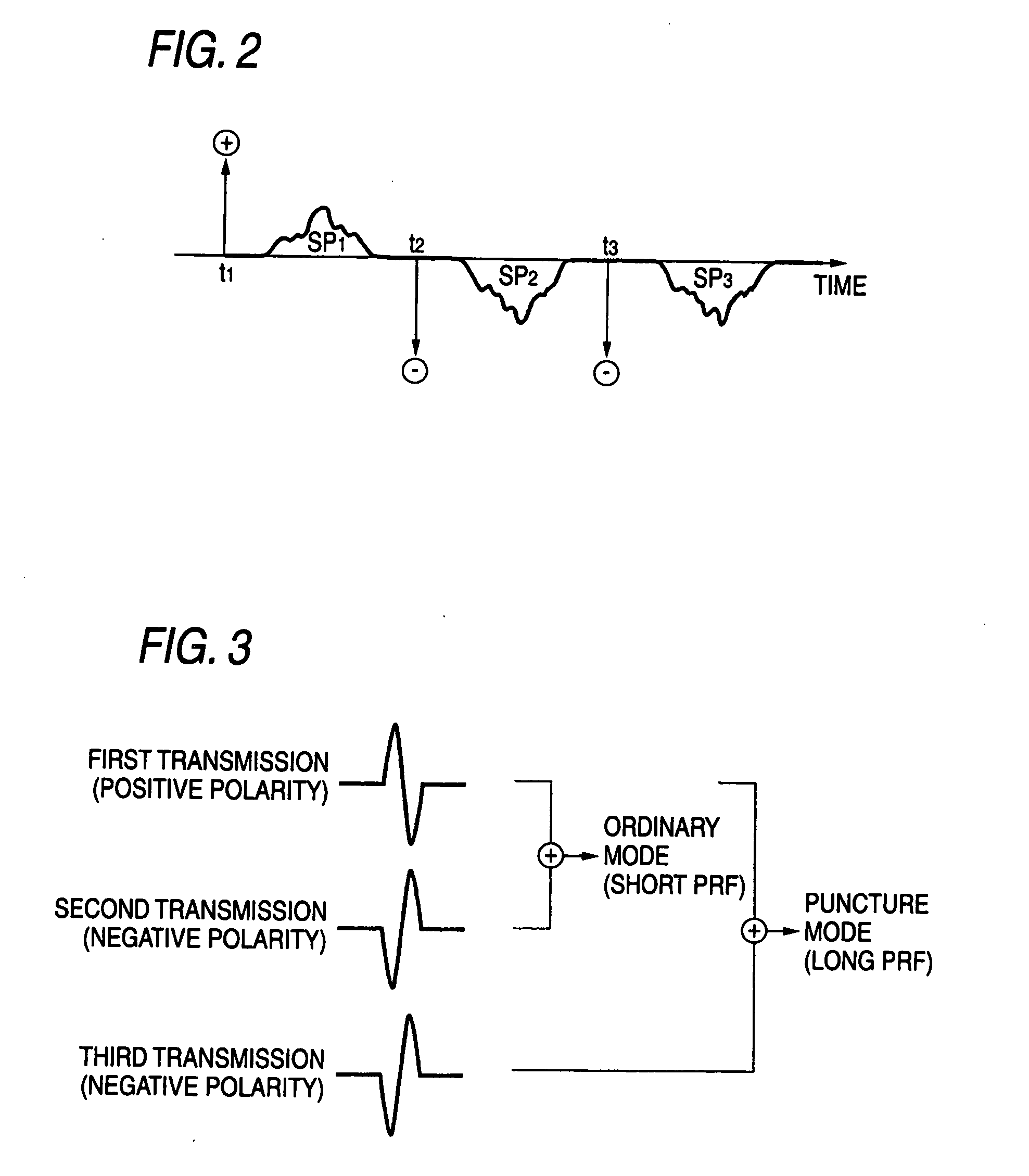
[0077] As shown in FIG. 7, ultrasonic pulses of inverted polarities or positive, negative and positive polarities are transmitted three times, for each of a plurality of ultrasonic scan lines by way of example....

third embodiment

[0080] Next, the third embodiment of the invention will be described. This embodiment consists in that imaging which enhances the visibilities of a puncture needle, etc. is performed by utilizing a dummy rate. Incidentally, the “dummy rate” is a rate at which an ultrasonic transmission is performed, but imaging utilizing a reflection wave obtained by the ultrasonic transmission is not performed, or at which the ultrasonic transmission itself is not performed.

[0081]FIG. 9 is a conceptual diagram for explaining a scan sequence which is executed by a puncture mode function according to the third embodiment. Besides, FIG. 10 is a conceptual diagram for explaining the signal processing of ultrasonic echo signals as is executed by the puncture mode function according to the third embodiment.

[0082] In this embodiment, as shown in FIG. 9 by way of example, three times of ultrasonic transmissions in positive polarity, in negative polarity, at the dummy rate and in negative polarity are per...


PUM


Abstract

Three times of ultrasonic transmissions are executed in positive, negative and negative polarities with reference to a predetermined rate period, for each of a plurality of ultrasonic scan lines, and echo signals caused and generated by the ultrasonic waves of the respective transmissions are received at the same rates. At each scan line, the echo signal based on the positive-polarity ultrasonic wave of the first transmission and the echo signal based on the negative-polarity ultrasonic wave of the second transmission are added up, thereby to generate an ordinary mode image. Besides, at each scan line, the echo signal based on the positive-polarity ultrasonic wave of the first transmission and the echo signal based on the negative-polarity ultrasonic wave of the third transmission are added up, thereby to generate puncture mode image data. The generated ordinary mode image and puncture mode image are displayed in a predetermined aspect.

Description

CROSS REFERENCE TO RELATED APPLICATIONS [0001] This is a Continuation Application of PCT Application No. PCT / JP2005 / 019321, filed Oct. 20, 2005, which was published under PCT Article 21(2) in Japanese. [0002] This application is based upon and claims the benefit of priority from prior Japanese Patent Applications No. 2004-306125, filed Oct. 20, 2004; and No. 2004-314345, filed Oct. 28, 2004, the entire contents of both of which are incorporated herein by reference.BACKGROUND OF THE INVENTION [0003] 1. Field of the Invention [0004] The present invention relates to enhancements in the reliability and accuracy of, for example, puncture under ultrasonic guide, and more particularly to an ultrasonic diagnostic equipment which is used for the betterment of the visibility of a puncture needle, and a method of controlling the equipment. [0005] 2. Description of the Related Art [0006] An ultrasonic diagnostic equipment is a medical image equipment with which the tomographic image of a soft t...

Claims


Application Information

Patent Timeline
IPC IPC(8): A61B8/00
CPCA61B8/08A61B8/0833A61B8/0841A61B8/463A61B8/488G01S15/8995G01S15/105G01S15/8959G01S15/8963G01S15/899G01S7/52038
Inventor NAKAYA, SHIGEMITSUKATAGUCHI, MUNEKIICHIOKA, KENICHIKAKEE, AKIHIROTAKIMOTO, MASAOSUMI, ATSUSHI
Owner KK TOSHIBA
Why Eureka
Try Eureka