Method of intracranial ultrasound imaging and related system

a technology of intracranial ultrasound and imaging method, applied in medical science, diagnostics, applications, etc., can solve the problems of dramatic attenuation of ultrasound signals, confined ultrasound signals and imaging, and high cost of intracranial imaging, etc., to overcome dramatic attenuation, improve image resolution, and safer method of intracranial ultrasound imaging

Inactive Publication Date: 2006-10-26
MICRO-STAR INTERNATIONAL
View PDF1 Cites 28 Cited by
  • Summary
  • Abstract
  • Description
  • Claims
  • Application Information

AI Technical Summary

Benefits of technology

[0023] The entire quality of ultrasound images depends on emitted and received signals. The prior art cannot overcome the attenuation issue when signals travel through the cranium, and thereby low-frequency signals are emitted and received to get low-resolution images. However, the claimed invention can improve the above issue. The claimed invention emits high-frequency signals and receives the low-frequency response from the echoed signal of the micro-bubble. Although the attenuation occurs when signals are emitted, the low-frequency response of the echoed signal is attenuated quite less than the high-frequency signal. Therefore, the claimed invention emits signals having proper strength, or adds proper strength to signals when signals are emitted, such that the low-frequency response can be generated after the ultrasound signal travels through the cranium, and clear blood vessel images can be generated. In o

Problems solved by technology

However, ultrasound signals are dramatically attenuated when transmitted through the cranium surrounding the brain.
Thus, ultrasound imaging technology is mostly applied in detecting whether the linear structure shifts or a ventricle expands inside the cranium, and is seldom applied in diagnosis of brain diseases, such as brain hematoma, arteriovenous aneurysm, arteriovenous malformation, etc.
Usually, expensive instruments, such as computer axial tomography (CAT) and nuclear magnetic resonance (NMR) devices, are used to take intracranial images.
However, ultrasound signals and imaging are thus confined

Method used


Image

  • Method of intracranial ultrasound imaging and related system
  • Method of intracranial ultrasound imaging and related system
  • Method of intracranial ultrasound imaging and related system

Examples


Embodiment Construction

[0029] Regarding the above description and detailed technology of the present invention, a best embodiment with drawings are disclosed as follows.

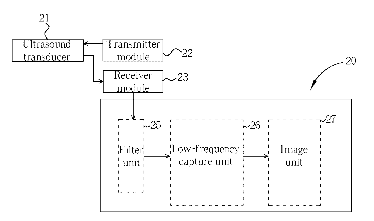
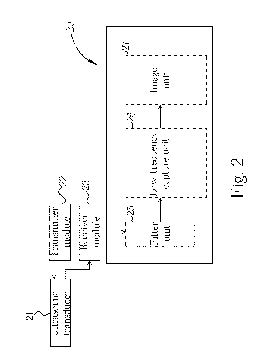
[0030] Shown in FIG. 2 is a diagram of an intracranial ultrasound imaging system implemented in an ultrasound system. To shed light on the present invention, the best embodiment detects a cranial blood vessel and generates a corresponding image. The contrast agent is injected into the cranial blood vessel by intravenous injection in advance so that the blood of the cranial blood vessel has a lot of micro-bubbles. The system comprises an ultrasound transducer 21, a transmitter module 22, a receiver module 23, and a signal processing module 20. The signal processing module 20 includes a filter unit 25, a low-frequency capture unit 26, and an image unit 27.

[0031] Please refer to FIG. 3, which is a flowchart of intracranial ultrasound imaging. The steps are as follows.

[0032] Step 31: The transmitter module 22 generates a driving signal to t...


PUM


Abstract

A method of intracranial ultrasound imaging applied in detecting a cranial blood vessel having blood filled with micro-bubbles formed by an injected contrast agent and generating blood vessel images includes: (1) emitting a plurality of ultrasound signals having bandwidths to the cranial blood vessel in sequence, (2) receiving an echoed signal from a micro-bubble, (3) performing a spectral analysis on the echoed signal and extracting a low-frequency response, the bandwidth of the low-frequency response similar to the bandwidth of the ultrasound signal, and (4) calculating a location and a depth of the micro-bubble in the cranium according to the low-frequency response and generating a corresponding blood vessel image.

Description

BACKGROUND OF INVENTION [0001] 1. Field of the Invention [0002] The present invention relates to a method of intracranial ultrasound imaging, and more particularly, to a method of intracranial ultrasound imaging by using an ultrasound contrast agent and a specific signal process. [0003] 2. Description of the Prior Art [0004] Medical ultrasound instruments have the advantages of safety and low price. Therefore, technology for ultrasound imaging has been widely used in clinical diagnosis, such as heart, abdominal region, and gynecological examinations. [0005] However, ultrasound signals are dramatically attenuated when transmitted through the cranium surrounding the brain. Thus, ultrasound imaging technology is mostly applied in detecting whether the linear structure shifts or a ventricle expands inside the cranium, and is seldom applied in diagnosis of brain diseases, such as brain hematoma, arteriovenous aneurysm, arteriovenous malformation, etc. Usually, expensive instruments, such...

Claims


Application Information

Patent Timeline
IPC IPC(8): A61B8/00
CPCA61B8/481A61B8/0808
Inventor CHOU, YI-HONGWU, CHUNG-YUOSU, TA-JUNGLO, MENG-TSUNG
Owner MICRO-STAR INTERNATIONAL
Why Eureka
Try Eureka