System for diagnosing and treating sleep apnea

Inactive Publication Date: 2006-10-26
WAYNE STATE UNIV
View PDF5 Cites 9 Cited by
  • Summary
  • Abstract
  • Description
  • Claims
  • Application Information

AI Technical Summary

Benefits of technology

[0032] The foregoing and other objects are achieved by this invention which provides a method of measuring upper airway r

Problems solved by technology

This labor intensive methodology, particularly since it applies a measure of subjectivity to a relatively few breaths, is not adequately precise to achieve an objective and fully reproducible determination of the presence of air flow limitation, and will often result in false diagnoses.
The known methods, however, are practicable only in sleep research laboratories, and typically are not available in the clinical sleep lab.
Clearly, the known process is time consuming, functions on a very limited data set, and is likely to produce erroneous results.
This condition generally causes repetitive disturbances during sleep resulting from inadequate flow of air into the lungs of the subject.
However, since such viscoelastic properties of the upper airway have not been thoroughly studied in the relevant literature, it is expected that an analysis b

Method used


Image

  • System for diagnosing and treating sleep apnea
  • System for diagnosing and treating sleep apnea
  • System for diagnosing and treating sleep apnea

Examples


Embodiment Construction

[0079] In developing the foundations of the present invention, the inventors herein consider a steady homogenous flow in a circular cylinder (the upper airway), with the assumption that the flow of air in the upper airway will expand without the loss or gain of heat. Consider a streamline of air, which connects two points M1, the upstream pressure, which is atmospheric pressure in the present model, and M2, the downstream pressure, which is equivalent to supraglottic pressure in the present model. For each point, there is a density (ρ), pressure (P), area (A), velocity (V) and flow (F) that characterize that point. In the modeling that follows, it should be noted that the goal is determination of the flow of the upper airway at the downstream pressure point, M2. Flow, which is constant throughout the upper airway, is given by:

Total Energy=Kinetic Energy [T]+Potential Energy [E]+Internal Energy  (1)

[0080] Internal energy=0

[0081] Differentiate both sides of equation (1) dK=dT+dE(2...


PUM


Abstract

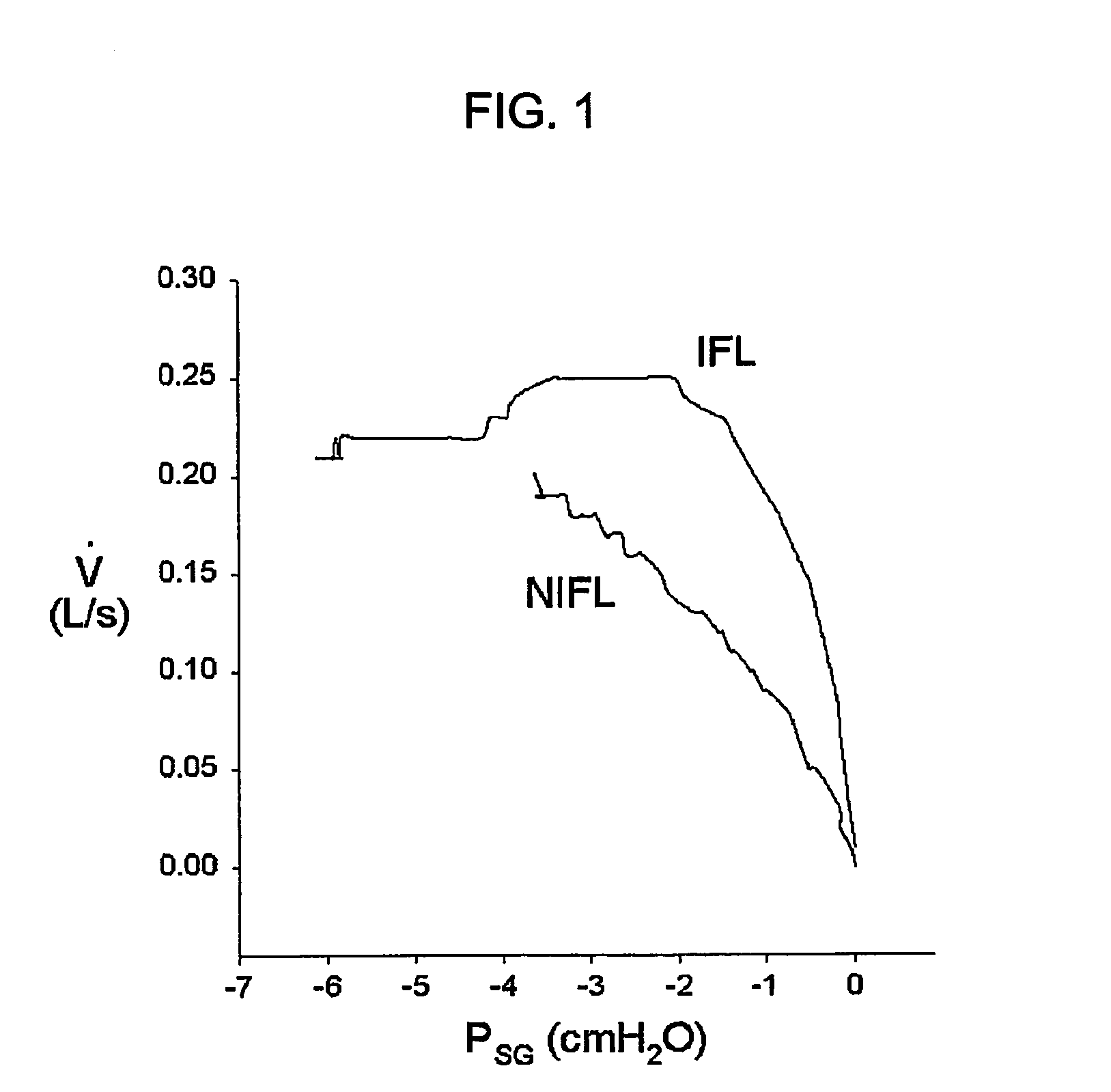
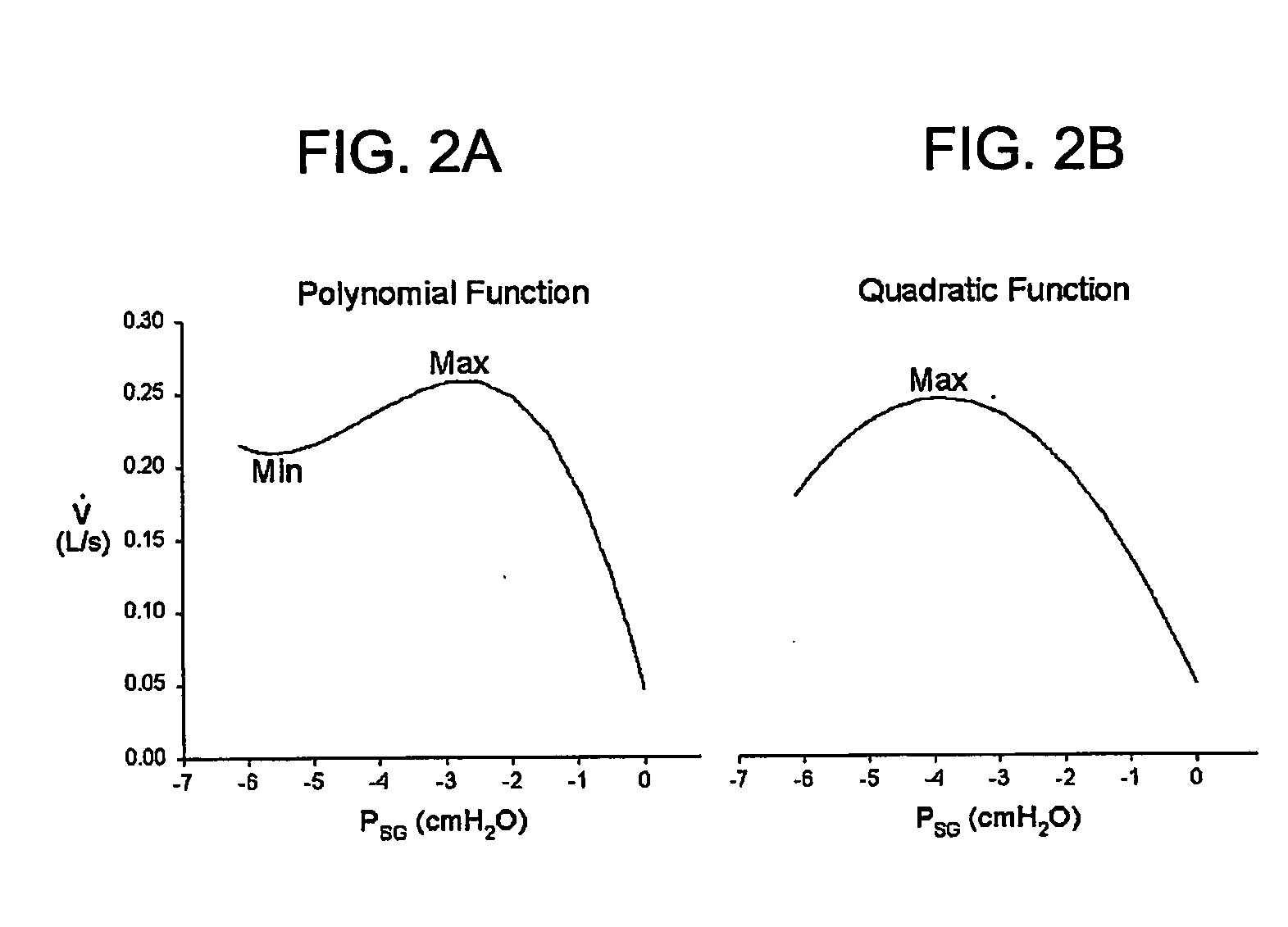
Two programs measure upper airway resistance using Resistance=Pressure/Flow. Raw flow and pressure data is divided into breaths and time adjusted so each breath starts with the value zero. Each breath is graphed as flow in the y-axis and time in the x-axis. The slope between points Flow=0 and Flow=0.20 is calculated. The resistance is the inverse of the slope. The second program determines whether a breath is flow limited or not. It also uses the flow and time data to perform a curve fitting to describe the flow-time in meaningful polynomial function F (P)=A t3+B t2+Ct+D. The derivative of this function is F′=3At2+2Bt+C. If the value of the derivative F′ at maximum flow is less than or equal zero, then it is a flow limited breath, otherwise, it is non flow limited breath. Also, the need for a pressure-monitoring catheter is obviated.

Description

RELATIONSHIP TO OTHER APPLICATION [0001] This application claims the benefit of the filing date of Provisional Application for U.S. Letters Patent Ser. No. 60 / 400,038 on Aug. 2, 2002 in the name of the inventors herein.GOVERNMENT RIGHTS [0002] A portion of this invention was made under contract of appointment awarded by The John D. Dingell Veterans Administration Medical Center in Detroit, Mich. wherein one or more inventors herein stand appointed by the Veterans Administration (“VA”) to perform work on behalf of the VA in its facilities. As such, the VA appointed inventor(s) are subject to the federal laws applicable to inventions and discoveries made in the course of the VA appointment. The government has certain rights in the corresponding portion of the present invention.BACKGROUND OF THE INVENTION [0003] 1. Field of the Invention [0004] This invention relates generally to systems for diagnosing sleeping disorders, and more particularly, to a system that is useful in effecting r...

Claims


Application Information

Patent Timeline
IPC IPC(8): A61B5/08A61B5/085
CPCA61B5/085
Inventor BADR, M SAFWAN
Owner WAYNE STATE UNIV
Why Eureka
Try Eureka