Auto CPAP

a technology of cpap and auto-cpap, which is applied in the field of auto-cpap, can solve the problems of increasing the risk of progressive deterioration of the airway aperture, and more severe respiratory disturbance before the patien

Inactive Publication Date: 2003-01-02
BREAS MEDICAL
View PDF4 Cites 49 Cited by
  • Summary
  • Abstract
  • Description
  • Claims
  • Application Information

AI Technical Summary

Benefits of technology

[0006] It is an object of the present invention to provide an improved method for automatically supplying continuous positive airways pressure to a patient.

Problems solved by technology

While high precision is welcome since rather small changes in breath pattern can be detected, a slower response increases the risk of progressive deterioration of the airway aperture, and thereby more severe respiratory disturbance before the patient is aroused.

Method used


Image

  • Auto CPAP
  • Auto CPAP
  • Auto CPAP

Examples


example 2

Algorithm

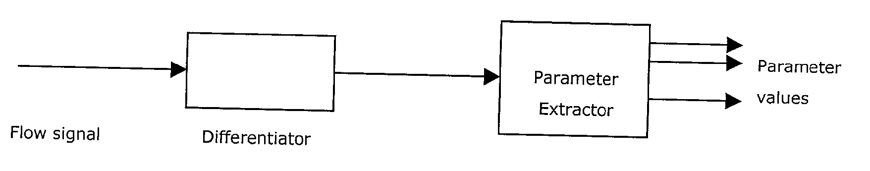
[0055] Data Acquisition.

[0056] Let the flow signal be a digitized version of the analog flow-signal sampled at .function..sub.s samples / second, giving a sequence of samples

x.sub.i, i=0,1, . . . ,

[0057] where x.sub.i is short for x(i.multidot.T) i.e. the sample at time instant i.multidot.T and

[0058] Preprocessing.

[0059] To reduce the influence of individual patient variations and to facilitate classification stability, the signal should pass a device to remove the signal mean. Any kind of steep edge high pass filter can be employed, thus the ideal differentiator is used for simplicity. The output from the differentiator, d, (and the input to the parameter extractor) will then be

d.sub.i=x.sub.i-x.sub.i-1

[0060] where i=0,1, . . . , and x.sub.-1.ident.0

[0061] Parameters.

[0062] The cepstrum coefficients have shown to well model the frequency content of the signal using only a few parameters (low order model). In addition, the dynamics of the cepstrum coefficients facilitate quan...

example 3

Hard Decision A

[0088] Let 64 map nodes be arranged in an 8.times.8 square grid and numbered 0 to 63 from the top left to the low right corner. Thus for example the map distance D.sub.0,1=1, D.sub.0,2=4 and D.sub.0,9=2 .

[0089] A large database is recorded containing flow-measures from several patients during all phases of sleep. The recordings are performed at 20 Hz and stored on a memory disk. The database will contain normal sleep breathing, flow limitations, snoring, yawning, coughing, various apneic events, but also mask leakage and other artifacts.

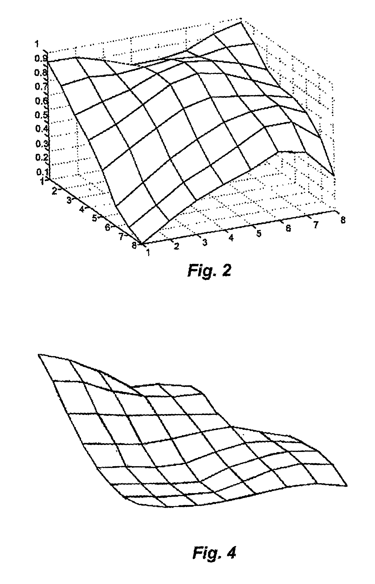
[0090] The database is analyzed sample for sample. The 20 Hz flow-signal is first passed through an ideal differentiator. A rectangular window of 180 samples is used to form basis for extracting 4 cepstrum coefficients (c.sub.1, . . . , c.sub.4) and the PET parameter. Thus the Feature Vector is a 5-dimensional vector with values extracted every 50 ms.

[0091] Samples are collected from the database in a random manner as long as the train...

example 4

Hard Decision B

[0099] This example is similar to the one described in example 1, but here a Hamming window of 180 samples is used instead of the rectangular. Furthermore the cepstrum coefficients are weighted to have approximately the same variances, whereas the PET parameter is given twice the variance of the cepstrum. This will give the PET parameter a little more importance than the rest of the parameters. The following weight function is employed:

w=[1 1.41 1.5 4 2]

[0100] The training is carried out exactly ass before, and the map response for a typical flow-limitation signal is shown in FIG. 4. In this case, nodes X,Y,Z will probably be labeled as a flow limitation region.


PUM


Abstract

A method for the detection and treatment of disordered breathing during sleep employs an artificial neural network (ANN) in which data related to breathing gas flow are analyzed. A respiratory circuit is established by connecting the patient to a continuous positive airway pressure (CPAP) system with pressurized breathing gas supply, the gas flow in the circuit is periodically sampled, one or several cepstrum parameters distinctive of various breathing patterns are periodically calculated; the parameter values are periodically fed to an ANN trained to recognize breathing patterns characteristic of sleep disordered breathing and are analyzed in the network, the CPAP pressurized breathing gas supply is controlled in response to the ANN output. Also disclosed is a corresponding apparatus.

Description

[0001] The present application claims the benefit of Swedish patent application No. SE 0003531-1 which was filed on Oct. 2, 2000 and is incorporated herein by reference.[0002] The present invention relates to method and an apparatus for the detection and treatment of disordered breathing during sleep, in particular to a method and apparatus employing an artificial neural network.[0003] U.S. Pat. No. 5,953,713 (Behbehani et al.), incorporated herein by reference, discloses a method for treating sleep disordered breathing comprising measuring a respiration-related variable at an interface placed over a patient's airway coupled to a pressurized gas, feeding cepstrum data obtained from the respiration related variable(s) into an artificial neural network trained to recognize patterns characterizing sleep disordered breathing; supplying pressurized gas to the patients airway in response to recognition of the artificial neural network of sleep disordered breathing. The sampling frequency ...

Claims


Application Information

Patent Timeline
Patent Type & Authority Applications(United States)
IPC IPC(8): A61B5/08A61B5/087A61M16/00
CPCA61B5/087A61B5/7267A61M16/0051A61M2016/0021A61M2230/10A61M2230/18A61M2230/205A61M2230/60A61M2230/62A61M16/026G16H50/70
Inventor EKLUND, OVEBERGFALK, HENRIK
Owner BREAS MEDICAL
Why Eureka
Try Eureka