Artificial functional spinal implant unit system and method for use

Inactive Publication Date: 2006-10-26
FLEXUSPINE
View PDF99 Cites 200 Cited by
  • Summary
  • Abstract
  • Description
  • Claims
  • Application Information

AI Technical Summary

Benefits of technology

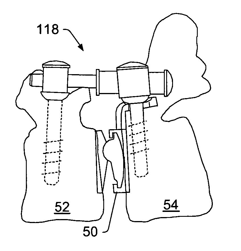
[0018] In some embodiments, the stabilization system may include a bridge. The bridge may couple to the first dynamic posterior stabilization system. The bridge may be configured to inhibit posterior migration of the first dynamic interbody device when the bridge is coupled to the first dynamic posterior stabilization system, and the first dynamic posterior stabilization system is coupled to vertebrae.
[0019] A method for installing a stabilization system for a human spine may include installing at least two dynamic interbody devices between a first vertebra and a second vertebra using a posterior surgical approach, and installing at least two dynamic posterior stabilization systems to couple the first vertebra to the second vertebra. In some embodiments, the method also includes coupling at least one dynamic interbody device to at least one of the dynamic posterior stabilization systems. The dynamic interbody device may be coupled to the dynamic posterior stabilization system using a bridge. In some embodiments, the inc

Problems solved by technology

However, genetic or developmental irregularities, trauma, chronic stress, and degenerative wear can result in spinal pathologies for which surgical intervention may be necessary.
Fusing two vertebrae together may result in some loss of motion.
Fusing two vertebrae together may also result in the placement of additional stress on one or more adjacent functional spinal units.
The additional stress may cause deterioration of an adjacent functional spinal unit that may result in the need for an additional surgical procedure or procedures.
A challenge of positioning a device between adjacent vertebrae using a posterior approach is that a device large enough to contact the end plates and slightly expand the space must be inserted through a limited space.
This challenge is often further heightened by the presence of posterior osteophytes, which may cause “fish mouthing” of the posterior vertebral end plates and result in very limited access to the disc.
A further challenge in degenerative disc spaces is the tendency of the disc space to assume a lenticular shape, which may require a larger implant than can be easily introduced without causing trauma to adjacent nerve roots.
The size of rigid devices that may safely be introduced into the disc space is thereby limited.
The anterior approach poses significant challenges as well.
Though the surgeon may gain very wide access to the interbody space from the anterior approach, this approach has its own set of complications.
The retroperitoneal approach usually requires t

Method used


Image

  • Artificial functional spinal implant unit system and method for use
  • Artificial functional spinal implant unit system and method for use
  • Artificial functional spinal implant unit system and method for use

Examples


Embodiment Construction

[0054] A “functional spinal unit” generally refers to a motion segment of a spine. The functional spinal unit may include two vertebrae, an intervertebral disc between the vertebrae, and the two facet joints between the vertebrae. An “artificial functional spinal unit” refers to a functional spinal unit where one or more of the components of the functional spinal unit are replaced by implants or devices that permit at least some motion of the spine. At least a portion of the intervertebral disc and / or one or both of the facet joints may be replaced by implants or devices during a spinal stabilization procedure.

[0055] As used herein, “coupled” includes a direct or indirect joining or touching unless expressly stated otherwise. For example, a first member is coupled to a second member if the first member contacts the second member, or if a third member is positioned between the first member and the second member.

[0056] A “dynamic interbody device” generally refers to an artificial i...


PUM

PropertyMeasurementUnit
Electrical resistanceaaaaaaaaaa
Dynamicaaaaaaaaaa

Abstract

A stabilization system for a human spine is provided comprising at least one dynamic interbody device and at least two dynamic posterior stabilization systems. The dynamic posterior stabilization system may be coupled on contralateral sides of vertebrae. In some embodiments, a bridge may couple a dynamic interbody device to a dynamic posterior stabilization system.

Description

PRIORITY CLAIM [0001] This application is a continuation-in-part of U.S. patent application Ser. No. 10 / 634,950 to Gordon et al., filed on Aug. 5, 2003 and entitled “Artificial Functional Spinal Unit Assemblies”, which is incorporated herein by reference.BACKGROUND [0002] 1. Field of the Invention [0003] Embodiments of the invention generally relate to functional spinal implant assemblies for insertion into an intervertebral space between adjacent vertebrae of a human spine, and reconstruction of the posterior elements to provide stability, flexibility, and proper biomechanical motion. More specifically, embodiments of the invention relate to artificial functional spinal units including an artificial intervertebral implant that can be inserted via a posterior surgical approach and used in conjunction with one or more dynamic posterior stabilization systems to approach an anatomically correct range of motion and segmental stiffness. Embodiments of the invention may also be inserted v...

Claims


Application Information

Patent Timeline
IPC IPC(8): A61F2/44A61B17/70A61B17/86A61F2/00A61F2/02A61F2/30
CPCA61B17/1671A61B17/746A61B17/7005A61B17/7008A61B17/7023A61B17/7032A61B17/7037A61B17/704A61B17/7041A61B17/7052A61B17/7064A61B17/86A61B17/8897A61B2017/0256A61F2/30767A61F2/30771A61F2/4405A61F2/4425A61F2002/30133A61F2002/30364A61F2002/30365A61F2002/30369A61F2002/30462A61F2002/30492A61F2002/30507A61F2002/30515A61F2002/30538A61F2002/3055A61F2002/30556A61F2002/30578A61F2002/30579A61F2002/30616A61F2002/30624A61F2002/30649A61F2002/30662A61F2002/3071A61F2002/30785A61F2002/30794A61F2002/30841A61F2002/443A61F2220/0025A61F2220/0033A61F2220/0075A61F2230/0015A61F2250/0006A61F2250/0007A61F2250/0009A61F2250/0085A61F2310/00407A61F2310/00796A61F2310/00976A61B17/1757A61F2/4684A61F2002/3079
Inventor GORDON, CHARLES R.HARBOLD, COREY T.HANSON, HEATHER S.WAGNER, ERIK J.
Owner FLEXUSPINE
Why Eureka
Try Eureka