Return path management system and method

a path management system and return path technology, applied in the field of return path management system and method, can solve the problems of reducing the burden of returning path servers b>70/b>, preventing the provider from fulfilling various demands of providers, and preventing the provider from fulfilling the transaction of order. the effect of excessive burden

Inactive Publication Date: 2006-10-26
ALTICAST
View PDF2 Cites 8 Cited by
  • Summary
  • Abstract
  • Description
  • Claims
  • Application Information

AI Technical Summary

Benefits of technology

[0005] Therefore, in order to avoid the above disadvantages, an object of the present invention is to provide a return path management system which provides intelligent plans to meet the various demands of the providers, and which highly reduces excessive burdens loaded to the return path server.

Problems solved by technology

However, in a case that the return path server 70 treats all the processes including delivery of the order information, user authentication, and billing, the capability of the server 70 should be very high, and delay of the transaction of the order may be caused.
This may be an obstacle to both the providers and the users.
Further, the return path server 70 does not satisfy various demands of the providers.
As thus, the return path server 70 wastes its capability on performing unnecessary tasks and the provider system becomes useless.
This is disadvantageous to the provider as well as the manager of the return path server.

Method used


Image

  • Return path management system and method
  • Return path management system and method
  • Return path management system and method

Examples


Embodiment Construction

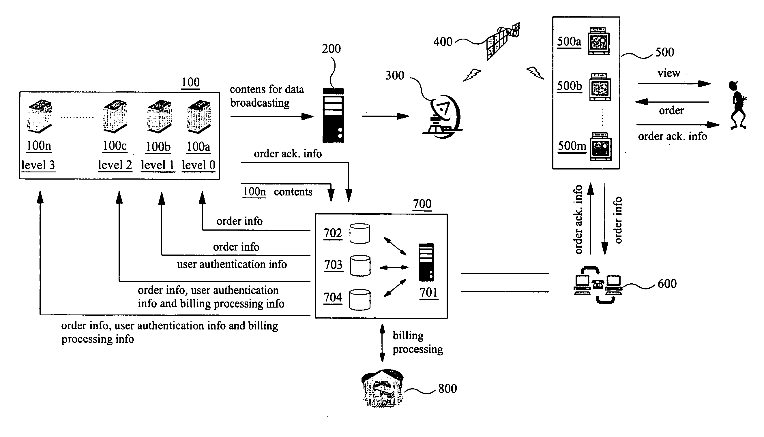
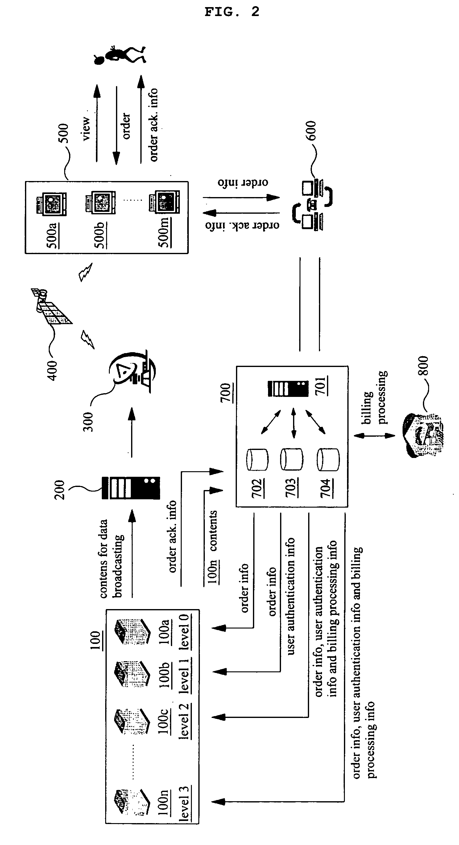
[0023]FIG. 2 is a schematic block diagram illustrating a return path management system in accordance with the present invention. A plurality of provider systems 100a-100n (totally “100”) and user televisions 500a-500n (totally, “500”) are connected to a return path management system 700. The provider systems 100 are leveled according to service levels requested from the providers. In FIG. 1, the provider system 100a is supposed to belong to a first level (“LEVEL 0”), the provider system 100b to a second level (“LEVEL 1”), the provider system 100c to a third level (“LEVEL 2”) and the provider system loon to a fourth level (“LEVEL 3”), respectively. IP addresses of the provider systems 100 and service levels of which the providers requested the return path management system 700 are maintained in a provider database 702.

[0024] Let us suppose that a user would like to order a good displayed on user television 500. The user transmits an order information to the return path management sy...


PUM


Abstract

There is provided a return path management system and method positioned between a user television and a provider system which delivers return paths from user televisions to provider systems in a packetized form. The return path management system comprises return path server, a provider database, a user database and a content database, wherein the provider database maintains providers information depending on levels which the provider systems belong to and which determine service levels, the user database maintains users information required for users authentication, a content database maintains contents information provided from the provider systems, and the return path server receives order information, identifies a provider to whom the received order information should be delivered, determines a service level based on the level which the provider belongs to in reference to the provider database, and performs interpretation and communication packetization of the order information depending on the determined service level. The return path management system according to the present invention can satisfy various demands of providers, because the system provides services dependent upon the provider systems. In addition, the return path management system according to the present invention can relieve excessive burdens loaded to return path servers caused by indiscriminate treatment of the return paths.

Description

TECHNICAL FIELD OF THE INVENTION [0001] The present invention relates to a return path management system and method. More specifically, the present invention relates a return path management system and method which provides intelligent operation of return paths. BACKGROUND OF THE INVENTION [0002] Internet is widely used for opinion polls, shopping, banking, and so on. Particularly, as you may know from the word, “internet is a sea of information,” various information are exchanged and shared through the internet. The internet became the essential tools of modern life. Accompanied with rapid distribution of the internet, development of bi-directional communications using a television has widely distributed the concept of “television commerce” (T-commerce). Television is a medium to which all the classes are intimate and easily accessible including the aged and housewives who are not intimate to a computer. [0003]FIG. 1 is a block diagram showing a conventional return path management ...

Claims


Application Information

Patent Timeline
Patent Type & Authority Applications(United States)
IPC IPC(8): H04N7/173H04N7/20G06F17/00
CPCH04N7/17318H04N21/2393H04N21/2542H04N21/812H04N21/25875H04N21/437H04N21/47815H04N21/2543G06Q30/06H04N7/173
Inventor LEE, ZINO
Owner ALTICAST
Why Eureka
Try Eureka