Position Detector and Position Detection Method

a position detector and position detection technology, applied in the field of position detectors, can solve the problems of large noise inputted to a servo system operated based on the indicator value of the position detectors, and achieve the effect of improving the accuracy of position detectors and accuracy

Active Publication Date: 2011-10-13
MURATA MASCH LTD
View PDF8 Cites 1 Cited by
  • Summary
  • Abstract
  • Description
  • Claims
  • Application Information

AI Technical Summary

Benefits of technology

[0011]In another example, each of the plurality of sensor units is a coil array. The position detector includes a common power supply for driving a plurality of coil arrays, a detection circuit for converting the outputs from the coil array into outputs of the detection circuit, and a switch for selectively inputting outputs from the plurality of coil arrays to use the detection circuit as a common detection circuit shared between the plurality of coil arrays. The switch is switched in the segment to convert the outputs from the plurality of coil arrays alternately into the outputs of the common detection circuit. In this manner, not only the detection circuit can be shared but also the difference in the indicator value of the position due to variation of the detection circuit can be eliminated. The difference in the indicator value of the position is due to the use of different detection circuits in addition to installation precision of marks and variation of each sensor unit. Therefore, by using the common detection circuit, the difference resulting from the use of detection circuits can be eliminated from the beginning.
[0012]In still another example, in the segment, a prediction computation unit is provided for performing extrapolation of time series data of positions based on an output from each coil array to positions at current time to determine a temporal current position of each coil array. In the smoothing unit, respective outputs of the temporal current positions of the coil arrays are combined to generate the position of the moving object. By sharing the detection circuit, since the sensor units are used alternately, in each of the individual sensor units, the cycle of obtaining the outputs from the sensor unit is doubled. In the meanwhile, in order to determine the position, it is necessary to obtain the indicator values from the plurality of sensor units at the same time. Therefore, by extrapolation of the indicator values from the sensor units to determine temporal current positions, the position of the moving object can be determined all the time without being affected by the influence resulting from sharing of the detection circuit.

Problems solved by technology

If the position changes discontinuously, large noises will be inputted to a servo system operated based on the indicator value from the position detectors disadvantageously.

Method used


Image

  • Position Detector and Position Detection Method
  • Position Detector and Position Detection Method
  • Position Detector and Position Detection Method

Examples


Embodiment Construction

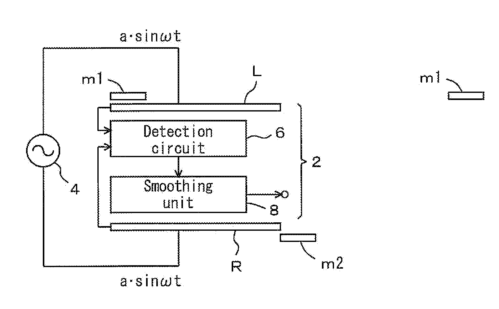
[0021]FIGS. 1 to 7 show the embodiment. In the drawings, reference numerals m1, m2 denote magnetic marks provided along left and right sides of a travel rail for moving objects (not shown), e.g., overhead traveling vehicles in the embodiment. For example, the mark is a combination of magnetizable material and non-magnetizable material, or a permanent magnet or the like. A position detector 2 is attached to a moving object (not shown), and made up of a pair of left and right coil arrays L, R (left and right sensor units), a common alternating current power supply circuit for driving the coil arrays L, R, a common detection circuit 6, and a smoothing unit 8.

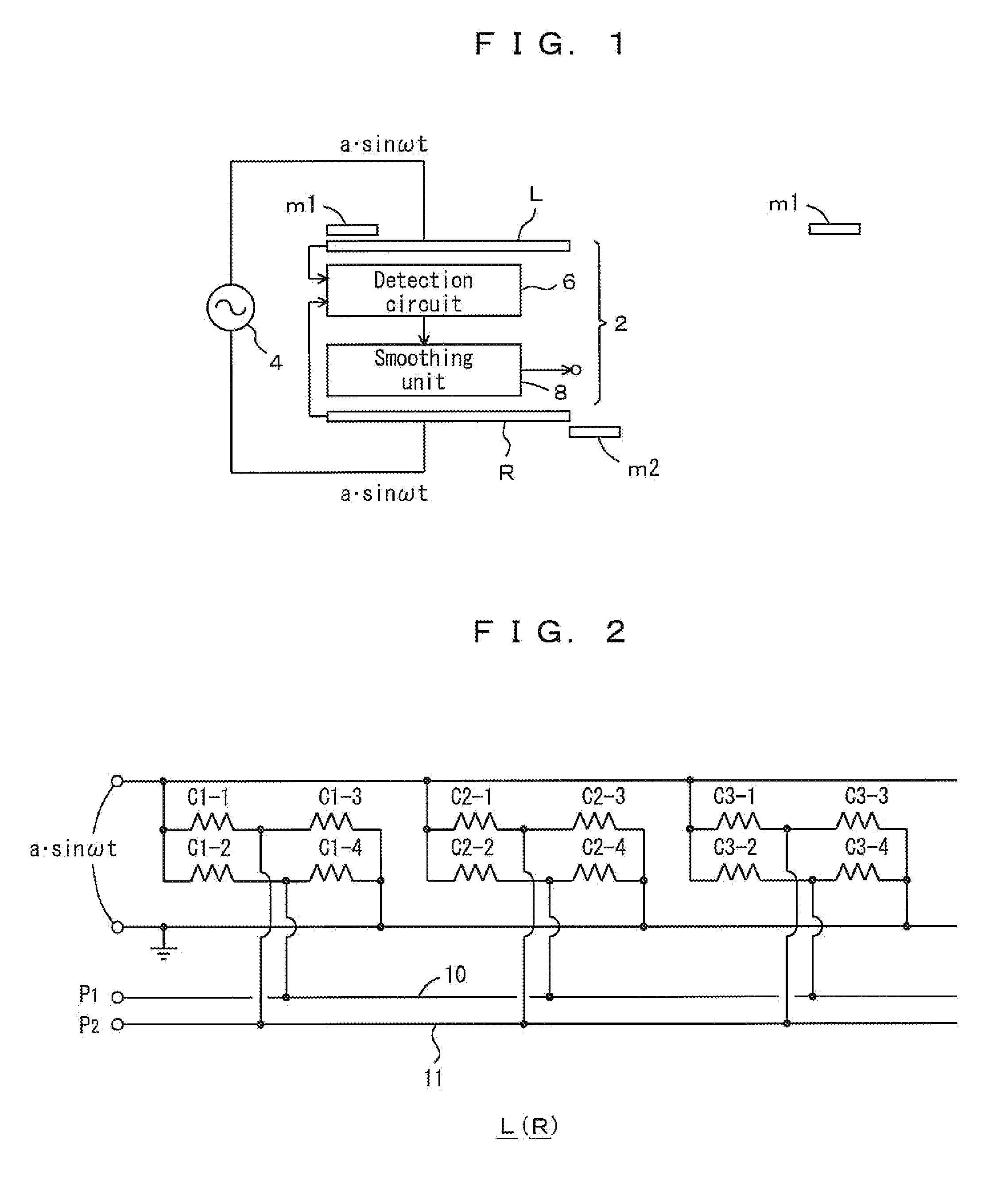
[0022]The coil arrays L, R have the same structure. A layout of coils of the coil arrays L, R is shown in FIG. 2. For example, four coils C1-1 to C1-4 are arranged in one set, and likewise, coils C2-1 to C2-4 are arranged in one set, and coils C3-1 to C3-4 are arranged in one set. The other coils are arranged in the same manner. Tw...


PUM


Abstract

A position detector having a plurality of sensor units is used. Each of the sensor units is configured to determine positions. The sensor units are selectively used for outputting positions of a moving object. Positional outputs are generated by combining outputs from a plurality of the sensor units in a segment where the plurality of sensor units output positions together, for allowing the positional outputs to change continuously from a start to an end of the segment.

Description

CLAIM OF PRIORITY[0001]This application claims priority under the Paris Convention and / or under 35 U.S.C. 119 (a)-(d) to Japanese Application Number 2010-091107, filed on Apr. 12, 2010, the entire contents of which are hereby incorporated by reference.FIELD OF THE INVENTION[0002]The present invention relates to a position detector for detecting positions of a moving object such as a traveling vehicle, a transfer apparatus, a head of a working machine or a workpiece. Further, the present invention relates to a position detection method.BACKGROUND ART[0003]The applicant developed a sensor for measuring positions of a moving object such as a traveling vehicle, a transportation apparatus, a transfer apparatus, a head of a working machine or a workpiece (e.g., Patent Publication 1: JP2009-2660A). This position detector uses a combination of magnetizable material and non-magnetizable material or a magnet or the like as a mark, and uses coil arrays to determine positions based on the mark....

Claims


Application Information

Patent Timeline
Patent Type & Authority Applications(United States)
IPC IPC(8): G01B7/00
CPCG01D5/24495B65G1/04G01D5/12G01D5/245G05D1/02
Inventor SHIMIZU, TETSUYA
Owner MURATA MASCH LTD
Why Eureka
Try Eureka