
Frozen beverage blender

a beverage blender and blender technology, applied in the field of frozen beverage blenders, can solve the problems of increasing the cutting time of ice cubes, and increasing so as to reduce the cutting noise of ice cubes in operation, reduce the cutting noise of ice cubes, and reduce the construction cost

Inactive Publication Date: 2006-11-02
JOYTEC
View PDF8 Cites 14 Cited by
  • Summary
  • Abstract
  • Description
  • Claims
  • Application Information

AI Technical Summary

Benefits of technology

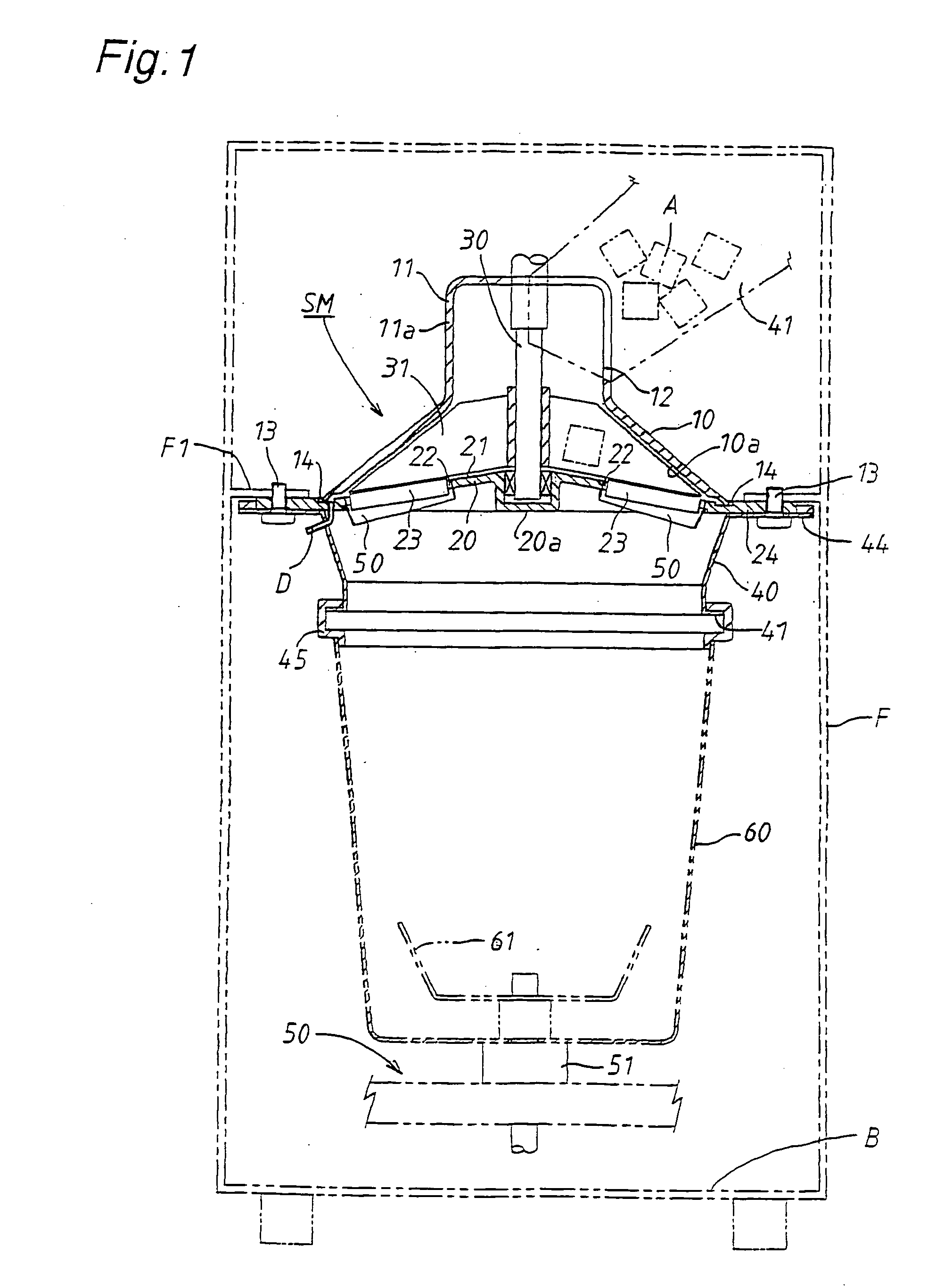
"The present invention provides a frozen beverage blender with an ice cutting mechanism that can quickly and efficiently cut ice cubes while reducing cutting noises. The blender includes an upper hood with a conical inner surface and a cutting disk with a conical upper surface, both of which are designed to cut ice cubes in a radial direction. A rotary shaft is supported on the cutting disk and a rotary plate is driven by the shaft to rotate along the cutting disk. The blender also includes a chute for introducing ice cubes falling from an ice storage container towards the cutting blade. The angle of the conical upper surface of the cutting disk is determined based on the size of the ice cubes to increase the centrifugal force acting on the ice cubes and facilitate rapid slicing. The cutting mechanism is small in size and can be easily removed for cleaning."

Problems solved by technology

In such operation of the cutting mechanism, cutting noises of the ice cubes become large.
The ice cubes falling on the axis center of the rotary plate causes the ice cubes in the container to rotate with the rotary plate, resulting in further increase of the cutting noises of ice cubes.
In the case that the conical casing is formed small in size to decrease the cutting noises of ice cubes, an amount of ice cubes sliced by the cutting blade per unit time is reduced, resulting an increase of cutting time of the ice cubes.
Accordingly, all the parts have to be removed from the upper portion of the cutting mechanism for washing, resulting in a trouble in washing of the parts.

Method used


Image

  • Frozen beverage blender
  • Frozen beverage blender
  • Frozen beverage blender

Examples


Embodiment Construction

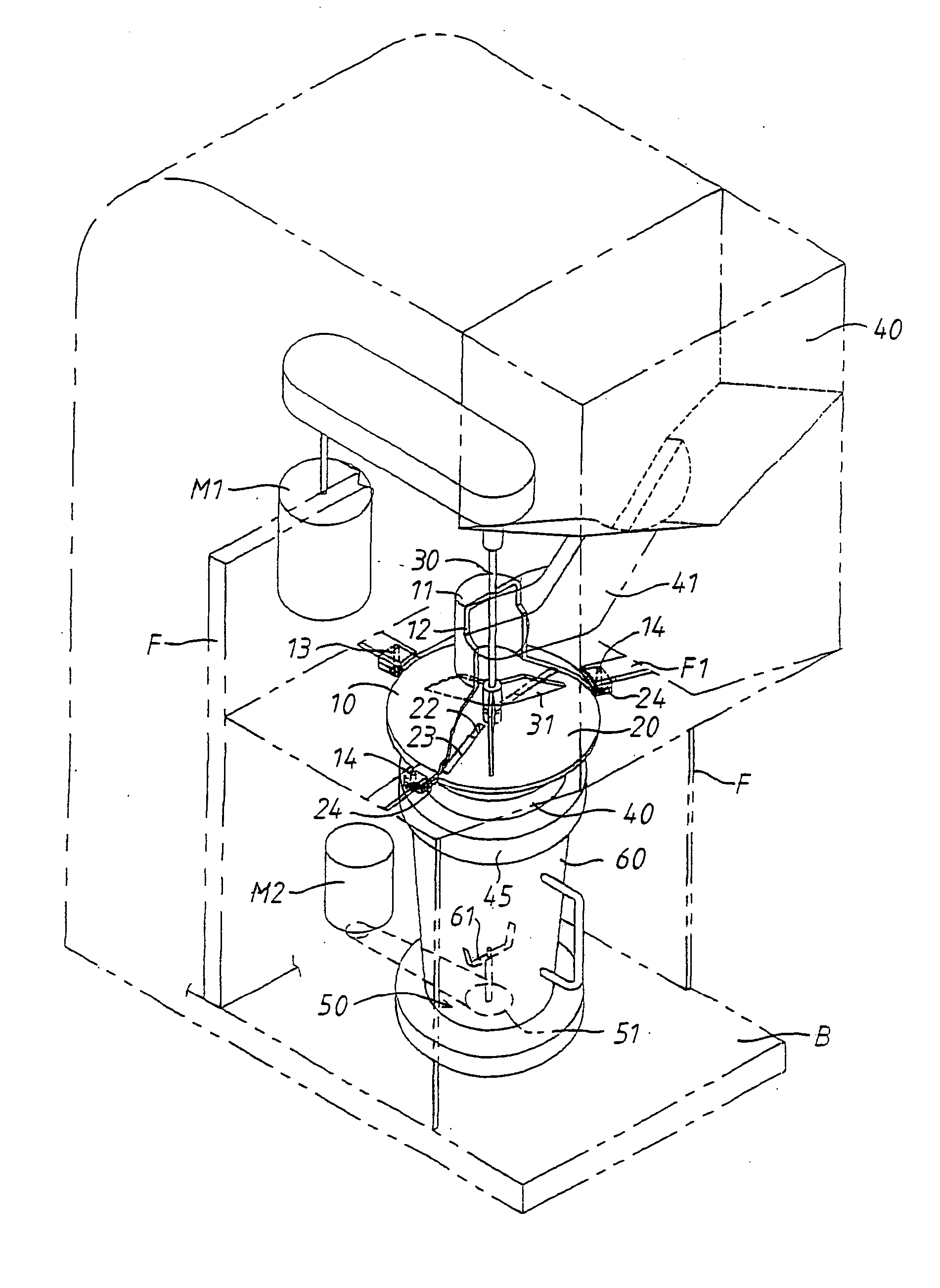
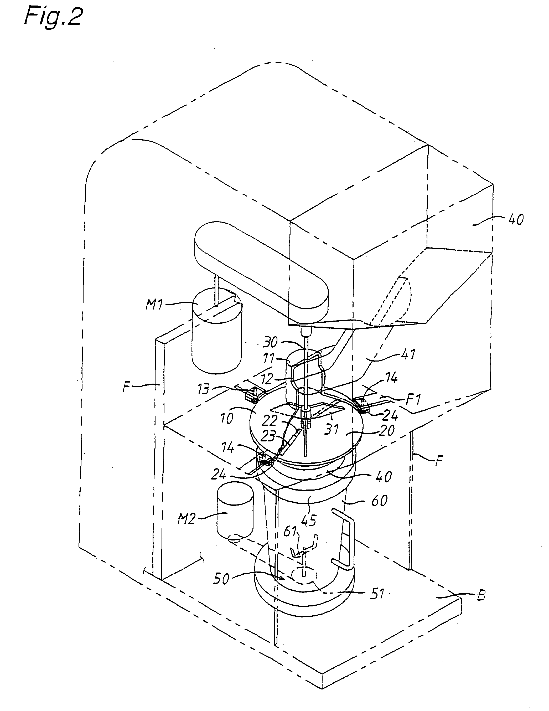
[0016] Illustrated in FIGS. 1 and 2 is a preferred embodiment of a frozen beverage blender equipped with an ice cutting mechanism in accordance with the present invention. The ice cutting mechanism in this embodiment includes an upright machine frame F mounted on a base structure B, an upper hood of aluminum die-casting horizontally mounted within the upright frame F to be removable downwardly, a cutting disk 20 of aluminum die-casting coupled at its lower end periphery with the lower end outer periphery of upper hood 10 to be removable downwardly, a rotary shaft 30 extended through the center of upper hood 10 and supported at its lower end on a boss portion formed on the head of cutting disk 20, and rotary plates 31 of aluminum die-casting driven by rotation of the rotary shaft 30 to rotate along the upper surface of cutting disk 20.

[0017] The upper hood 10 has a downwardly inclined conical inner surface 10a and a cylindrical head portion 11 formed at its peripheral wall 11a with ...


PUM


Abstract

A frozen beverage blender equipped with an ice cutting mechanism including an upright machine frame mounted on a base structure, an upper hood horizontally mounted on the upper portion of the machine frame to be detachable downwardly, the upper hood having a downwardly inclined conical inner surface, a cutting disk coupled at its lower end outer periphery with a lower end outer periphery of the upper hood to be detachable downwardly, the cutting disk having a conical upper surface downwardly inclined from its center and being provided with a cutting blade mounted thereon in such a manner that the edge of the cutting blade is positioned upward at a radial slit formed in the cutting disk, a rotary shaft vertically extending through the center of the upper hood and being supported at its lower end on the head of the cutting disk, and a rotary plate driven by the rotary shaft to rotate along the upper surface of the cutting disk, wherein the upper hood has a cylindrical head portion formed with an inlet opening for introducing ice cubes falling from an ice storage container located above the machine frame, and wherein a cylindrical lower hood is integrally assembled with the lower end outer periphery of the upper hood through the lower end outer periphery of the cutting disk, and a beverage container put on the base structure to store an amount of beverage is detachably engaged at its upper end opening with the lower end outer periphery of the lower hood to receive ice pieces sliced by and dropping from the cutting blade.

Description

BACKGROUND OF THE INVENTION [0001] 1. Field of the Invention [0002] The present invention relates to a frozen beverage blender equipped with a cutting mechanism of ice cubes. [0003] 2. Description of the Prior Art [0004] As is disclose in Japanese Utility Model Registration No. 252637, a cutting mechanism of this kind adapted for use in a frozen beverage blender is composed of an ice storage container placed above a conical casing, a cutting blade mounted on an upwardly inclined peripheral wall of the conical casing, a rotary plate driven by rotation of a rotary shaft to rotate along the inner surface of the conical casing, and a chute arranged at a front side of a beverage blender to introduce ice cubes falling from the ice storage container and drop ice pieces sliced by the cutting blade just under the cutting blade. [0005] In the cutting mechanism described above, a large amount of ice cubes dropped in the conical casing are moved upward along the inner wall of the conical casing...

Claims


Application Information

Patent Timeline
Patent Type & Authority Applications(United States)
IPC IPC(8): B02C17/00B02C17/16A47J43/042A47J43/046
CPCA47J43/042Y10S241/17A47J43/046F25C5/12
Inventor NAKATO, YUTAKA
Owner JOYTEC
Learn More