Permanent magnet type motor
a permanent magnet electric motor and permanent magnet technology, applied in the direction of rotating magnets, magnetic circuit rotating parts, synchronous machines with stationary armatures, etc., can solve the problems of reducing the cogging torque, and reducing the control performance of electric motors, so as to reduce the leakage flux and the induced voltage constant ratio. the effect of not being reduced
- Summary
- Abstract
- Description
- Claims
- Application Information
AI Technical Summary
Benefits of technology
Problems solved by technology
Method used
Image
Examples
embodiment 1
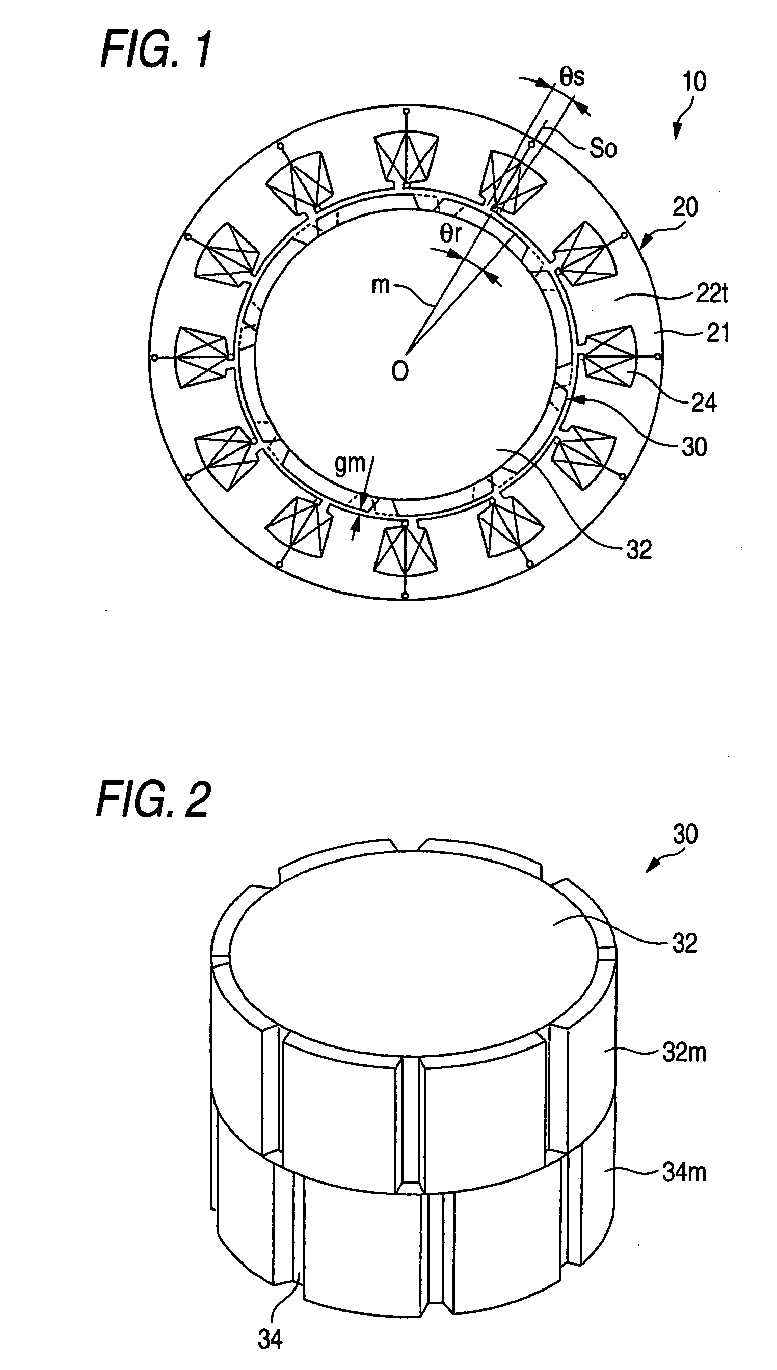
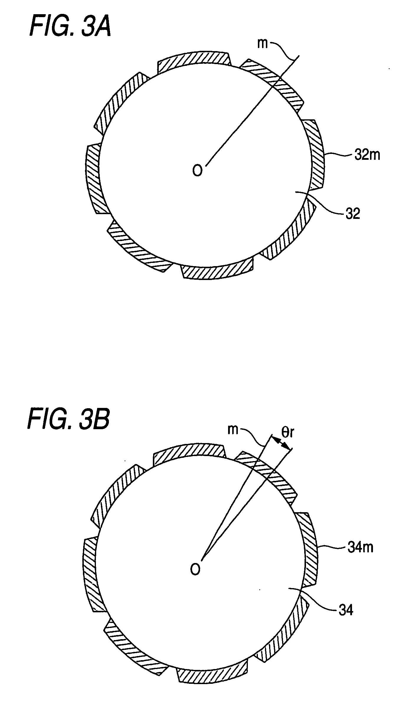
[0029] Referring to FIGS. 1 to 5, an embodiment 1 of the present invention will be described below. FIG. 1 is a side cross-sectional view of a permanent magnet electric motor according to the embodiment 1 of the invention. FIG. 2 is a perspective view of a rotor in the permanent magnet electric motor as shown in FIG. 1. FIGS. 3A and 3B are plan views of the rotor in the permanent magnet electric motor as shown in FIG. 1. FIG. 4 is a perspective view of a stator in the permanent magnet electric motor as shown in FIG. 1. FIGS. 5A-5C are plan views of an upper stage stator block, a middle stage stator block, and a lower stage stator block as shown in FIG. 4.
[0030] In FIGS. 1 to 5, the permanent magnet electric motor 10 is formed of an electromagnetic steel plate that is punched with the stator magnetic pole teeth 22t connected to a thin connecting portion, and comprises a stator iron core 21 of cylindrical shape, a stator 20 with 12 magnetic poles formed by winding a plurality of stat...
embodiment 2
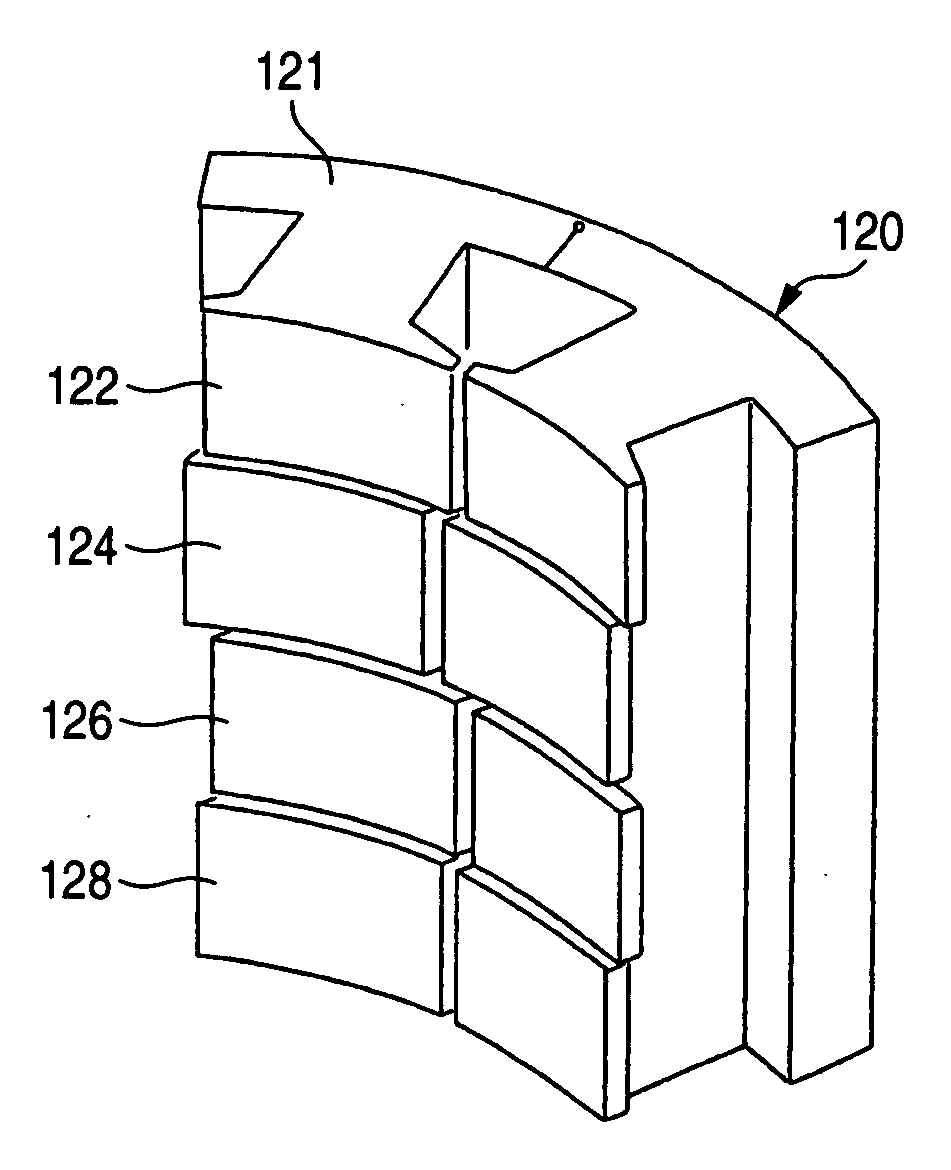
[0052] Another embodiment of the present invention will be described referring to FIG. 11. FIG. 11 is a perspective view of the stator according to another embodiment.
[0053] In the above embodiment 1, the fundamental wave component of cogging torque is reduced by providing the rotor iron cores 32 and 34 with the rotor skew angle θr, and the second order higher harmonic wave component of cogging torque is reduced by providing the stator iron cores 22, 24 and 26 with the stator skew angle θs.
[0054] In this embodiment, the rotor 30 is the same as in the embodiment 1, but the stator 120 is divided into four stator iron cores 122, 124, 126 and 128, whereby the second order higher harmonic wave component of cogging torque is reduced by providing the stator skew angle θs.
[0055] The stage skew angle between the stator iron core 122 and the top portion of stator magnetic pole teeth in the stator iron core 126 and between the stator iron core 124 and the top portion of the stator magnetic ...
embodiment 3
[0056] Referring to FIG. 12, another embodiment of the invention will be described below. FIG. 12 is a side cross-sectional view of a permanent magnet electric motor according to another embodiment of the invention.
[0057] In the above embodiments 1 and 2, the permanent magnet electric motor has the stator 20 disposed outside and the rotor 30 disposed inside the stator 20.
[0058] The permanent magnet electric motor 200 according to this embodiment has a rotor 230 disposed outside and a stator 220 disposed inside the rotor 230.
[0059] In the above embodiments 1 to 3, the rotor 30, 230 is formed with the skew angle θr for removing the fundamental wave component of cogging torque, and the stator 20, 220 is formed with the skew angle θs for removing the second order higher harmonic wave component of cogging torque. Conversely, the rotor 30, 230 may be formed with the skew angle θs for removing the second order higher harmonic wave component of cogging torque, and the stator 20, 220 may ...
PUM
 Abstract
Description
Claims
Application Information
 - R&D
- Intellectual Property
- Life Sciences
- Materials
- Tech Scout
- Unparalleled Data Quality
- Higher Quality Content
- 60% Fewer Hallucinations
Browse by: Latest US Patents, China's latest patents, Technical Efficacy Thesaurus, Application Domain, Technology Topic, Popular Technical Reports.
© 2025 PatSnap. All rights reserved.Legal|Privacy policy|Modern Slavery Act Transparency Statement|Sitemap|About US| Contact US: help@patsnap.com


