Piezoelectric resonator and piezoelectric oscillator

a piezoelectric oscillator and piezoelectric resonator technology, applied in the direction of final product manufacture, generator/motor, printed circuit aspects, etc., can solve the problems of insufficient relaxation of stress, and easy cracks in solder connection

Inactive Publication Date: 2006-11-02
TOYO TSUSHINKI
View PDF6 Cites 11 Cited by
  • Summary
  • Abstract
  • Description
  • Claims
  • Application Information

AI Technical Summary

Benefits of technology

[0016] According to a first aspect of the invention, a piezoelectric resonator comprises: an insulating package provided with a concave portion at a lower region; an piezoelectric resonator element installed within the concave portion of the insulating package; a lid sealing a lower opening of the concave portion; and; a metal lead terminal of which a upper region is electromechanically connected and fixed to an outer terminal installed at the circumference of the insulating package, and a lower region is protruded downward from the lid. The metal lead terminal includes a drooping portion extending along the side of the insulating package and a connecting member extending from the lower part of the drooping portion. The drooping portion is not constrained from the connecting member, and the drooping portion and the connecting member are capable of elastically deformed.
[0017] In the first aspect of the invention, the upper end of the metal lead terminal may be electromechanically connected and fixed to the outer terminal installed at the upper area or the side area of the insulating package.
[0018] In the first aspect of the invention, the entire outer surface of the insulating package may be covered with a resin.
[0019] In the first aspect of the invention, the metal lead terminal may be a J lead terminal of which the connecting member is curved.
[0020] According to a first aspect of a piezoelectric oscillator of the invention, it comprises: a piezoelectric resonator including: an insulating package provided with a concave portion at a lower region; a piezoelectric resonator installed within the concave portion of the insulating package; a lid sealing a lower opening of the concave portion; a metal lead terminal of which a upper region is electromechanically connected and fixed to the an outer terminal installed at the circumference of the insulating package, a lower region is protruded downward from the lid; an IC chip face-down bonded to the upper surface of the piezoelectric resonator. The metal lead terminal includes a drooping portion extending along the side of the insulating package and a connecting member extending from the lower part of the drooping portion. The drooping portion is not constrained from the connecting member, and the drooping portion and the connecting member are capable of elastically deformed.
[0021] In the first aspect of the piezoelectric oscillator of the invention, an external terminal installed at the upper surface of the piezoelectric resonator may be connected to the upper end of the metal lead terminal and the IC chip may be mounted on the upper end of the metal lead terminal via a connecting member.

Problems solved by technology

The stress easily yields cracks in the solder connection.
This problem further causes insufficient relaxation of the stress due to thermal expanding difference between the printed circuit board and the terminal.

Method used


Image

  • Piezoelectric resonator and piezoelectric oscillator
  • Piezoelectric resonator and piezoelectric oscillator
  • Piezoelectric resonator and piezoelectric oscillator

Examples


first embodiment

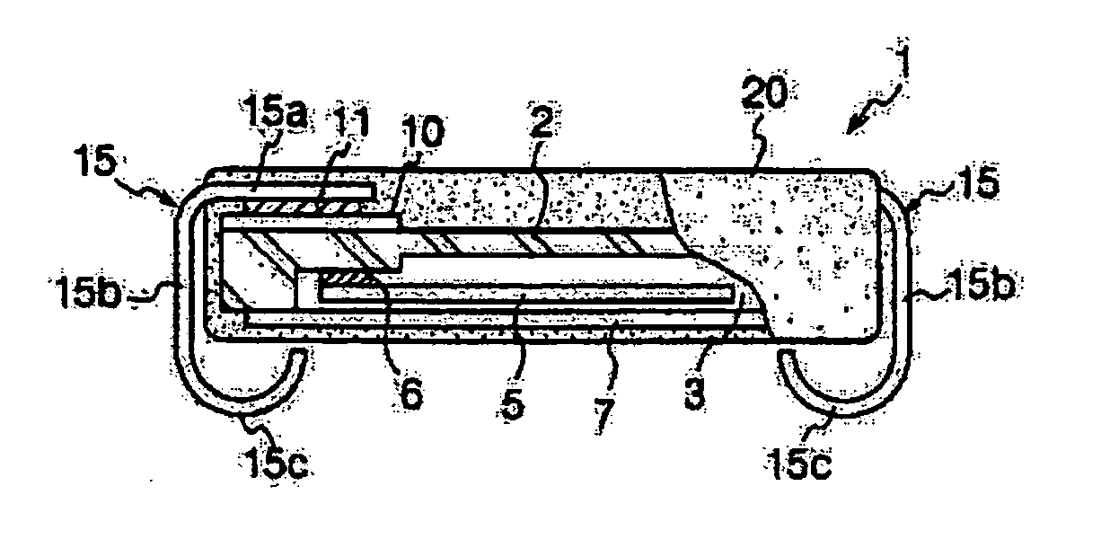
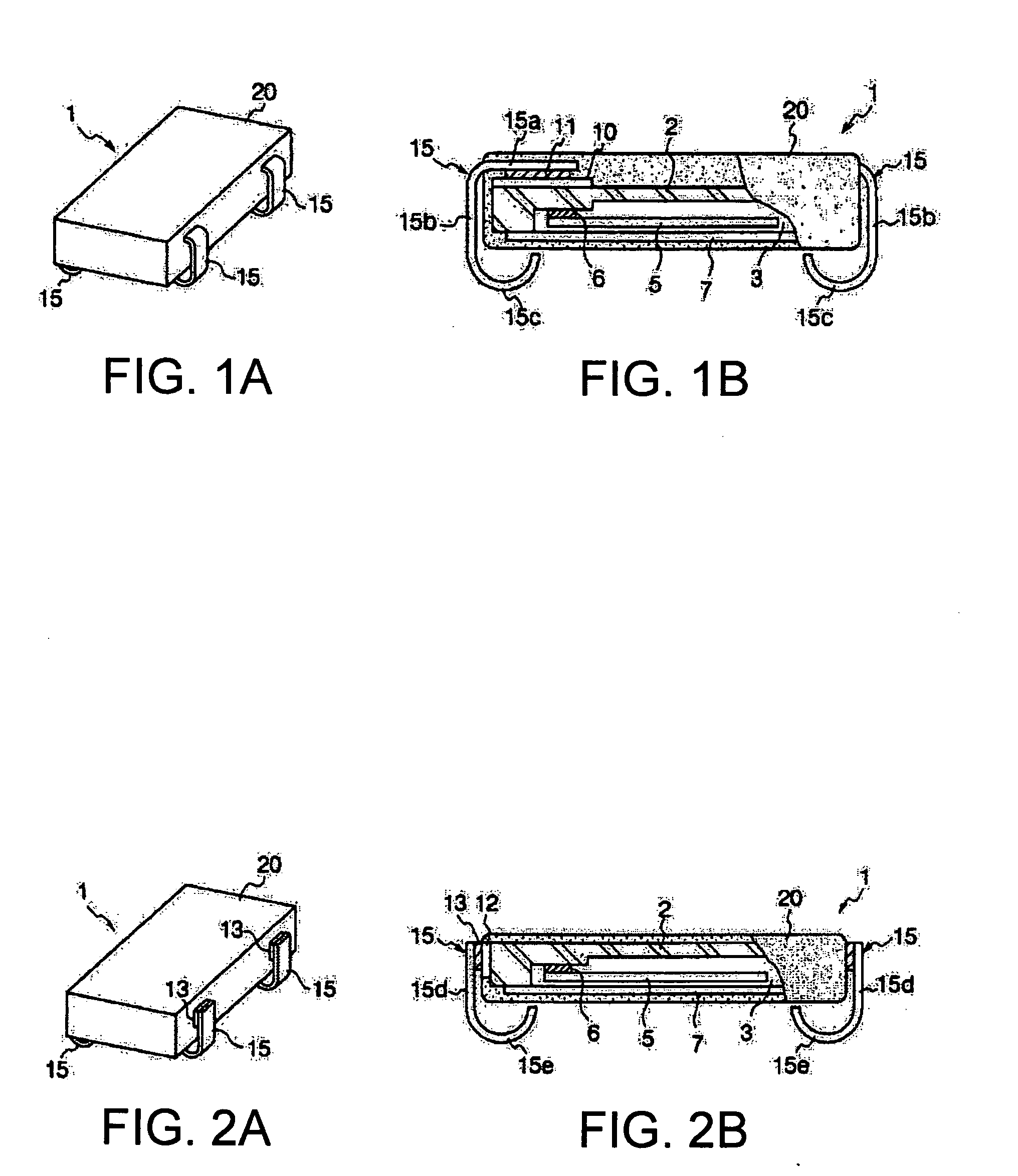
[0058]FIG. 1A is an outer perspective view of a quartz resonator (a piezoelectric oscillator) as a surface mounting electronic device of the invention and FIG. 1B is a cross section of it.

[0059] A quartz resonator 1 comprises a ceramic package 2, a quartz resonating element 5, a connecting member 6 and a lid 7. The resonating quartz element 5 has a structure in which exciting electrodes and others are formed on a quartz substrate and is mounted on a connecting pad not shown in the figure within a concave portion 103 in the ceramic package 101.

[0060] Further it is fixed by the connecting member 106 composed of conductive adhesives. The concave portion 3 is sealed by the lid 7 made of a metal. Further, a plurality of metalized upper terminals (external terminals) 10 is formed on the upper surface of the ceramic package 2. The upper terminal 10 is fixed and connected to a mounting terminal 15 composed of a metal lead terminal via a brazing filler metal 11. At least two upper terminals...

second embodiment

[0064] Next, FIG. 2A is an outer perspective view of a quartz resonator (a piezoelectric oscillator) as a surface mounting electronic device of the invention and FIG. 2B is a cross section of it.

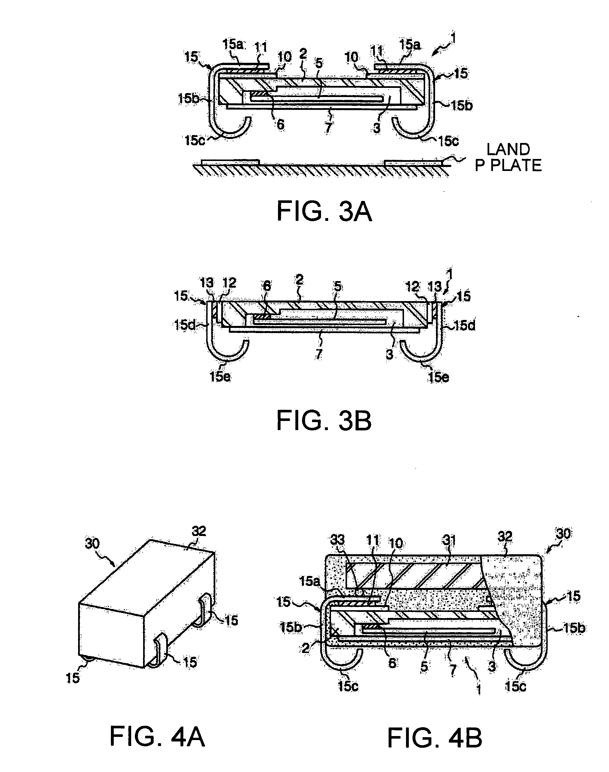
[0065] The difference between the first embodiment shown in FIG. 1 and the second embodiment shown in FIG. 2 is that the J lead terminal 15 is fixed and connected to the side terminal (an external terminal) 12 installed on the side surface of the ceramic package 2 with a brazing filler metal 13. The side terminal 12 is connected to a connecting pad within the concave portion 3 connected to the electrode on the quartz resonating element 5 via an internal conductive member not shown in the figure.

[0066] The J lead terminal 15 comprises the base 15d extending upward and downward, and the connecting member 15e in which the lower part of the base 15d is curved into the inside of the ceramic case. The base 15d is fixed and connected to the side terminal 12 with a brazing filler metal 13.

[0067] T...


PUM


Abstract

A piezoelectric resonator comprises: an insulating package provided with a concave portion at a lower region thereof, an piezoelectric resonator installed within the concave portion of the insulating package; a lid sealing a lower opening of the concave portion; and a metal lead terminal of which a upper region is electromechanically connected and fixed to the outer terminal installed at the outer surface of the insulating package, and a lower region thereof is projected downward from the lid. The metal lead terminal includes a drooping portion extending along the side surface of the insulating package and a connecting member extending from the lower part of the drooping portion. The drooping portion is not constrained from the connecting member, and the drooping portion and the connecting member are capable of elastically deformed.

Description

BACKGROUND OF THE INVENTION [0001] 1. Technical Field [0002] The present invention relates to improving a surface-mounting electronic device such as a piezoelectric resonator and a piezoelectric oscillator. In particular, it relates to a surface-mounting electronic device using lead members like J leads as terminals for connection. [0003] 2. Related Art [0004] In mobile telecommunication device market, major manufactures promote modular designing of parts groups for each function, in considering commonality of parts among devices regarding packaging, maintenance and handling. [0005] Further, down sizing as well as low manufacturing cost is strongly required accompanied with promoting modular designing. [0006] In particular, promoting modular designing is enhanced in the area of electronic parts such as standard oscillators, PLL circuits, and synthesizers where hardware and functions are already established and high stability and high performance are required. Furthermore, packaging ...

Claims


Application Information

Patent Timeline
Patent Type & Authority Applications(United States)
IPC IPC(8): H01L41/053
CPCH03B5/36H05K3/3426H05K2201/10651H05K2201/10083H05K2201/0311Y02P70/50
Inventor TANAKA, YOSHIAKI
Owner TOYO TSUSHINKI
Why Eureka
Try Eureka