Device, system and method for realizing on screen display translucency

Active Publication Date: 2006-11-02
HON HAI PRECISION IND CO LTD
View PDF12 Cites 0 Cited by
  • Summary
  • Abstract
  • Description
  • Claims
  • Application Information

AI Technical Summary

Benefits of technology

[0013] By employing the above-described device, system and method, OSD transl

Problems solved by technology

However, the alpha blending process needs a multiplication device with a complicated operation.
The change can result in image displa

Method used


Image

  • Device, system and method for realizing on screen display translucency
  • Device, system and method for realizing on screen display translucency
  • Device, system and method for realizing on screen display translucency

Examples


Embodiment Construction

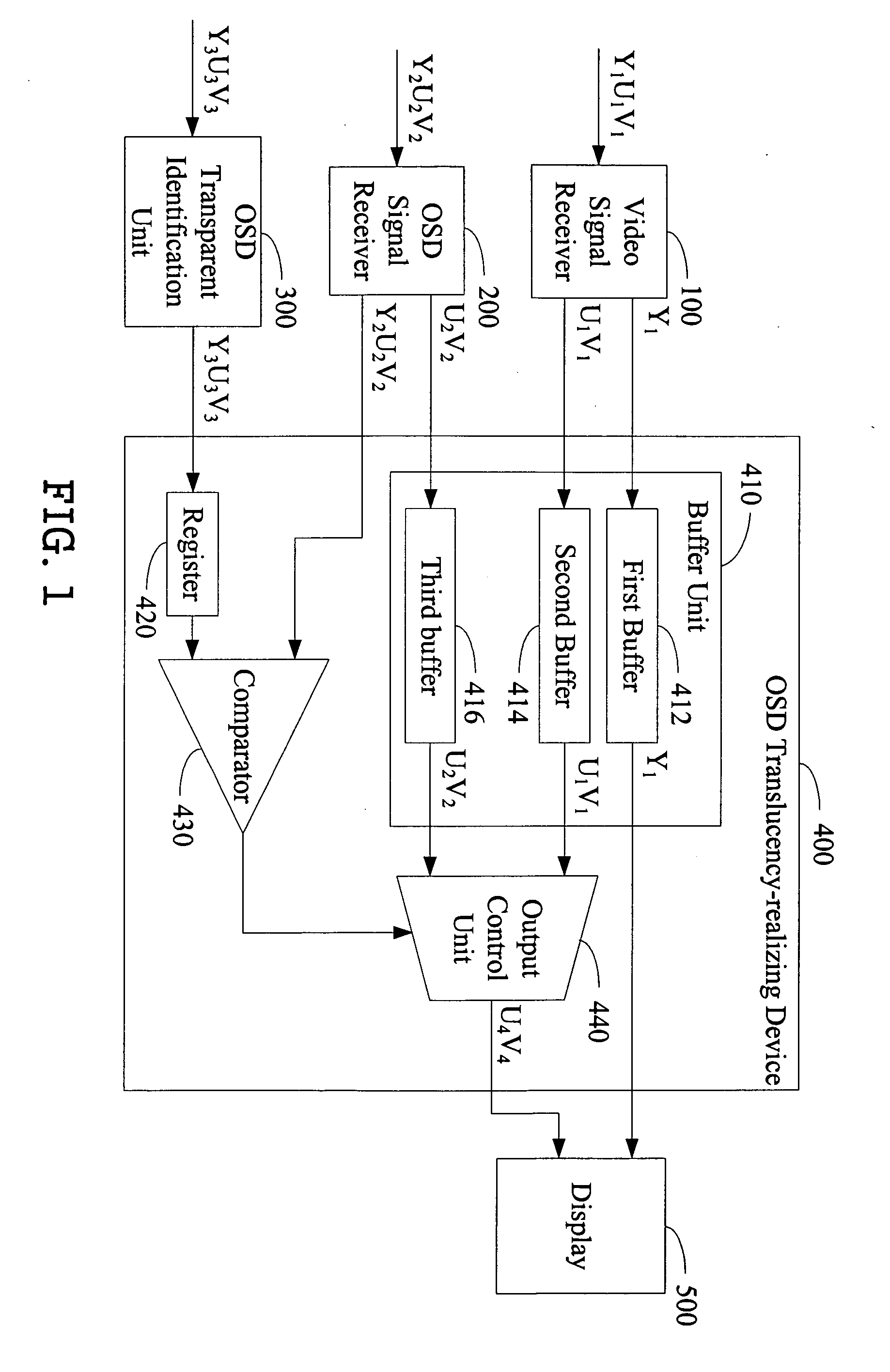
[0020]FIG. 1 shows a block diagram of a system for realizing OSD translucency according to an exemplary embodiment of the present invention. In the exemplary embodiment, the system includes a video signal receiver 100, an OSD signal receiver 200, an OSD transparent identification unit 300, an OSD translucency-realizing device 400, and a display 500. The OSD translucency-realizing device 400 includes a buffer unit 410, a register 420, a comparator 430, and an output control unit 440. In the exemplary embodiment, the buffer unit 410 includes a first buffer 412, a second buffer 414, and a third buffer 416.

[0021] The video signal receiver 100 is used for receiving video signals Y1U1V1, and for outputting the Y1U1V1 signals to the buffer unit 410. The Y1 component of the Y1U1V1 signals is transmitted to the first buffer 412, and the U1V1 components of the Y1U1V1 signals are transmitted to the second buffer 414. The OSD signal receiver 200 is used for receiving OSD signals. In the exempl...


PUM


Abstract

A device for realizing on screen display (OSD) translucency in video signals includes a comparator (430) and an outputting control unit (440). The comparator (430) is used for receiving OSD signals and identification signals on a background color selected to be transparent in the OSD signals, identifying the background color in the OSD signals based on the identification signals, and generating a control signal based on the identification. The outputting control unit (440) is connected to the comparator (430), and is used for receiving UV components of the OSD signals, UV components of the video signals, and the control signal, and for selectively outputting UV data of the video signals or UV data of the OSD signals according to the control signal. By employing the device, OSD translucency can be efficiently realized through simple operations. A related system and method for efficiently realizing OSD translucency are also provided.

Description

BACKGROUND OF THE INVENTION [0001] 1. Field of the Invention [0002] The present invention relates to devices, systems and methods for processing images, and particularly to a device, system and method for realizing on screen display (OSD) translucency. [0003] 2. Related Art [0004] On screen display (OSD) technology is widely used in image processing devices such as TVs (televisions), PCs (personal computers), and mobile terminals. The OSD displays additional information such as a channel selection and display time of the image processing device. [0005] However, conventional OSD techniques have a shortcoming in that the OSD partially covers images being shown on the screen of the image processing device. Referring to FIG. 5, image (e) schematically illustrates an original image of an image processing device, and image (f) schematically illustrates an OSD image. Image (g) shows the OSD image without a background color. When the OSD image and the original image are combined as shown in...

Claims


Application Information

Patent Timeline
IPC IPC(8): G09G5/00G09G5/02H04N5/265H04N9/74
CPCG09G5/026H04N5/44504H04N21/44004H04N21/4318H04N21/4355H04N9/76
Inventor SU, CHI-CHUNG
Owner HON HAI PRECISION IND CO LTD
Why Eureka
Try Eureka