Temperature control method and temperature control device

a temperature control and temperature technology, applied in the direction of process control, lighting and heating equipment, instruments, etc., can solve the problems of increasing the electric power consumed by and increasing the power consumption of a single semiconductor device (semiconductor chip), so as to achieve high accuracy, fast temperature control, the effect of efficient evaluation and/or testing

Inactive Publication Date: 2006-11-02
SOCIONEXT INC
View PDF2 Cites 13 Cited by
  • Summary
  • Abstract
  • Description
  • Claims
  • Application Information

AI Technical Summary

Benefits of technology

[0039] According to the temperature control method and device of the present invention, the heat conduction part having the first and second principal surfaces is used, the first principal surface having a configuration corresponding to that of the controlled part, such as the electronic part, and the second principal surface having an area larger than that of the first principal surface, and the heating unit and the cooling unit are disposed on the second principal surface of the heat conduction part. The heat produced from the controlled part is effectively absorbed by the heat conduction part, so that the heat is spread and equalized. The heating and cooling of the controlled part is performed by the heating unit and the cooling unit. Even for the controlled part with a large calorific value, or the controlled part with a large consumption power to treat, the temperature control can be carried out quickly in response to a change of the consumption power of the controlled part.
[0040] Accordingly, even when the controlled part has a large consumption power, the evaluation and / or testing of the temperature characteristics can be efficiently carried out with high accuracy.
[0041] When the heating unit and the cooling unit are operated simultaneously in order to set the temperature of the controlled part at a predetermined temperature, the difference of temperature of the controlled part produced in such a case under the heating unit and the cooling unit is conducted horizontally and equalized within the heat conduction part, and it is directed to the controlled part on the first principal surface. Thereby, the temperature of the controlled part can be controlled with good accuracy and promptness.

Problems solved by technology

While the electronic parts are required to attain high integration and advanced features, the environment and conditions in which they are used have become severe.
As a result, the increase of the electric power which is consumed by a single semiconductor device (semiconductor chip), i.e., the raise of the power consumption, is progressing.
The operation of a semiconductor device causes a temperature rise due to the self-heating and the surrounding environment, and the operation of the semiconductor device becomes unstable.
Therefore, the checking and compensating of the operating characteristics cannot be performed to various kinds of semiconductor devices with which the heat generating characteristics differ under the controlled temperature condition or at a constant low temperature.
Also when conducting the testing for checking and compensating the operating characteristic of a semiconductor device, the power consumption, i.e., the temperature of a semiconductor device, will change with the respective testing items sharply.
The heat capacity of the heating medium part is comparatively small, and the rapid temperature change in the electronic part cannot be absorbed or diffused.
And the electronic part is subjected to the rapid cooling by the thermoelectric effect element, and a thermal damage will be given to the electronic part.
The passage of the heat conduction is comparatively long, the heat capacity is comparatively large, and it is difficult to achieve rapid cooling or rapid heating of the semiconductor device.
According to the above composition, there is no unit for cooling directly the semiconductor device (the evaluated / tested electronic device) to a lower temperature, and it is difficult to conduct the above-mentioned evaluation or testing of the semiconductor device in such a cold condition.
The heat conduction passage is long, and the heat capacity is comparatively large, and it is difficult to carry out prompt cooling or heating of the semiconductor device.

Method used


Image

  • Temperature control method and temperature control device
  • Temperature control method and temperature control device
  • Temperature control method and temperature control device

Examples


first embodiment

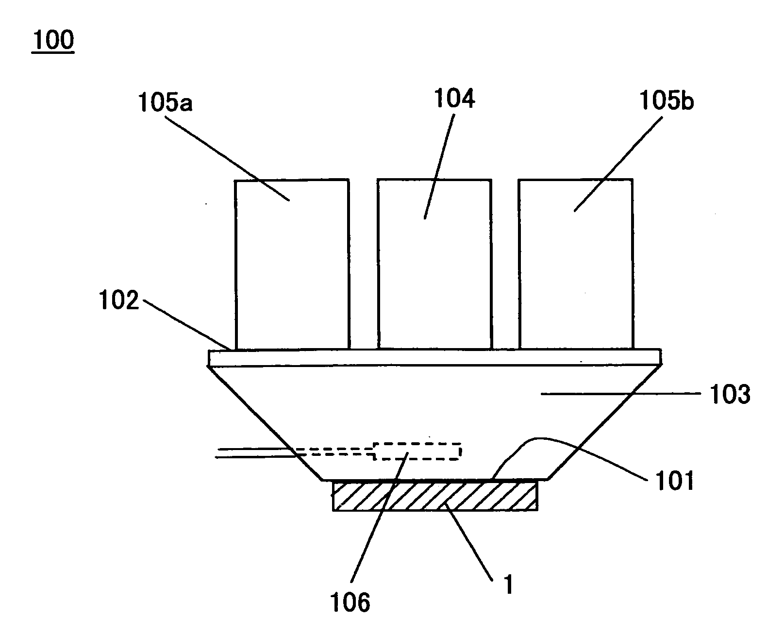
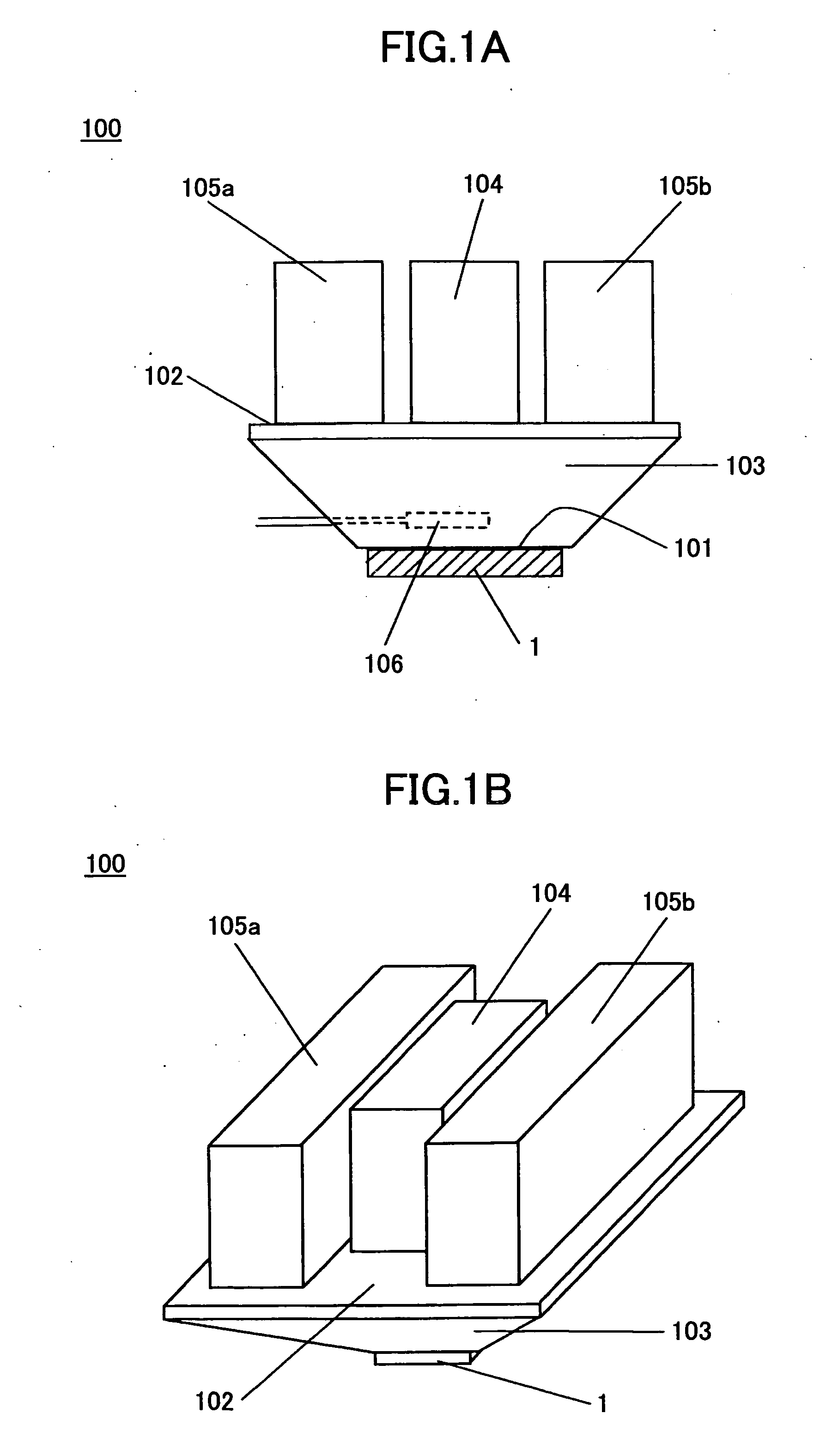
[0074] The first embodiment of the temperature control device according to the invention will be explained using FIG. 1A and FIG. 1B.

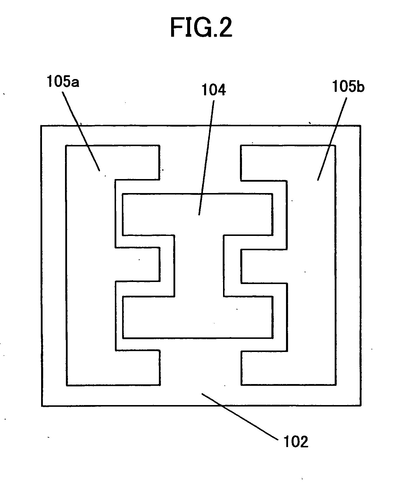
[0075] As shown in FIG. 1A and FIG. 1B, the temperature control device 100 in this embodiment comprises the heat conduction part 103 having the first principal surface 101 and the second principal surface 102, the heating unit 104, and the cooling units 105a and 105b. The first principal surface 101 can be contacted to the electronic part 1 which is the object of temperature control, such as a semiconductor device. The second principal surface 102 is opposite to the first principal surface 101.

[0076] The heating unit 104 is disposed almost in the central part on the second principal surface 102, and the cooling units 105a and 105b are disposed on the second principal surface 10 so that the heating unit 104 and the cooling units 105a and 105b are arranged side by side.

[0077] In the above-mentioned composition, the electronic part 1 (which is the cont...

second embodiment

[0117] The second embodiment of the temperature control device according to the invention will be explained using FIG. 8A and FIG. 8B.

[0118] In FIG. 8A and FIG. 8B, the elements which are the same as corresponding elements in the first embodiment are designated by the same reference numerals, and a description thereof will be omitted.

[0119] The temperature control device 200 in this embodiment is configured, as shown in FIG. 8A and FIG. 8B, so that the heating unit 104 and the cooling unit 105 are supported pivotably on the second principal surface 102 with the heat conduction part 103 which has the first principal surface 101 that can contact to the electronic part 1 which is the target of temperature control, such as a semiconductor device, and the second principal surface 102 opposite to the first principal surface 101 is provided.

[0120] In the above-mentioned composition, heat conduction part 103 is formed with thermally conductive high materials, such as copper (Cu) or alumi...

third embodiment

[0134] The third embodiment of the temperature control device according to the invention will be explained using FIG. 9A and FIG. 9B.

[0135] In FIG. 9A and FIG. B, the elements which are the same as corresponding elements in the first and second embodiments are designated by the same reference numerals, and a description thereof will be omitted.

[0136] The temperature control device 300 in this actual condition mode as shown in FIG. 9A and FIG. 9B, the heat conduction part 103 which has the first principal surface 101 that can contact to the electronic part 1 which are the targets of temperature control, such as a semiconductor device, and the second principal surface 102 opposite to the first principal surface 101, the heating unit 104 supported by support portion 301 on the second principal surface 102, and the cooling unit 105 are provided.

[0137] It is supported by the rotation shaft 302, and disk 303 made pivotable in parallel with the second principal surface 102 of the heat c...


PUM


Abstract

In a temperature control method, a controlled part is arranged to contact a first principal surface of a heat conduction part. The heat conduction part has the first principal surface and a second principal surface opposite to the first principal surface. The first principal surface has a configuration corresponding to a configuration of the controlled part. The second principal surface has an area larger than an area of the first principal surface. At least one of a heating unit and a cooling unit is driven to set the controlled part at a predetermined temperature. The heating unit and the cooling unit are disposed on the second principal surface of the heat conduction part so that the heating unit and the cooling unit are arranged side by side.

Description

CROSS-REFERENCE TO RELATED APPLICATIONS [0001] This application is based upon and claims the benefit of priority of Japanese Patent Application No. 2005-132550, filed on Apr. 28, 2005, the entire contents of which are herein incorporated by reference. BACKGROUND OF THE INVENTION [0002] 1. Field of the Invention [0003] The present invention generally relates to a temperature control method and a temperature control device for use in the temperature control method. In particular, the present invention relates to a temperature control method in which a controlled part, such as an electronic part, is subjected to heating or cooling so that the controlled part is set at a given temperature different from a normal temperature, in order to carry out evaluation and / or testing of the controlled part. [0004] 2. Description of the Related Art [0005] In the following, the electronic parts are semiconductor integrated circuit devices, such as IC and LSI, which will be referred to as semiconducto...

Claims


Application Information

Patent Timeline
Patent Type & Authority Applications(United States)
IPC IPC(8): H05K7/20
CPCG01R31/2874H01L2924/0002H01L2924/00B60M3/02
Inventor MARUYAMA, SHIGEYUKIMISAWA, HIROSHIKOHASHI, NAOHITO
Owner SOCIONEXT INC
Why Eureka
Try Eureka