Reference signal generator and method

a reference signal and generator technology, applied in the direction of electrical control, apparatus for force/torque/work measurement, instruments, etc., can solve the problems of difficult to achieve greater resolution, difficult to predict ignition timing, insufficient angular resolution of 1, 6, and 10 degrees noted above, etc., to reduce exhaust gas pollution, reduce the slope of the change in rotational speed, and improve the effect of precision

Inactive Publication Date: 2010-11-30
A&D CO LTD
View PDF14 Cites 0 Cited by
  • Summary
  • Abstract
  • Description
  • Claims
  • Application Information

AI Technical Summary

Benefits of technology

[0014]In accordance with these configurations, the time interval to be predicted between teeth is predicted by reflecting the rotational trend of the same tooth of the same cycle in the past in the time interval data of the immediately preceding tooth interval. Therefore, a highly precise reference signal in which the characteristics of the predicted tooth and the rotational trend are incorporated into the immediately preceding time interval, and real time ECU-based measurement and control can be achieved.
[0017]In this manner, reference signal precision can be improved and highly accurate measurement and control can be carried out because the slope of the change in rotational speed can be added between a plurality of reference signals generated between teeth by changing the mode for generating a reference signal in accordance with the rotational trend of past cycles of the same tooth.
[0020]In this manner, the amount of variation in the rotational speed is used as the rotational trend, this is reflected in the mode for generating a reference signal, and the reference signal can be made to follow changes in the rotational speed. The difference from the reference signal generated for the tooth that predicts the next time interval is thereby smoothed and the measurement and control precision is improved for the particular case in which the amount of change in the rotational speed is considerable.
[0025]The slope of the change in rotational speed is greater particularly when the rotational speed of the engine is low in comparison to when the rotational speed is high. Measurements and control must therefore be carried out immediately with good precision in accordance with changes in the rotational speed in order to reduce exhaust gas pollution, improve fuel consumption, and achieve other aims. Therefore, it is expected that the present invention will be sufficiently useful for conventional ECU-based real time measurement and control.
[0026]In accordance with the reference signal generator and method according to the present invention, the time interval to be predicted between teeth is predicted by reflecting the rotational trend of the same tooth of the same cycle in the past in the time interval data of the immediately preceding tooth interval. Therefore, a highly precise reference signal in which the characteristics of the predicted tooth and the rotational trend are incorporated into the immediately preceding time interval, and real time ECU-based measurement and control can be achieved.
[0028]The slope of the change in rotational speed is greater particularly when the rotational speed of the engine is low in comparison with when the rotational speed is high. Measurements and control must therefore be carried out immediately with good precision in accordance with changes in the rotational speed in order to reduce exhaust gas pollution, improve fuel consumption, and achieve other aims. Therefore, it is expected that the present invention will be sufficiently useful to the ECU in order to highly precise measurement and control in real time.

Problems solved by technology

However, the controller of such and internal combustion has the following technical problems.
Angular resolutions such as 1, 6, and 10 degrees noted above are insufficient for precise measurement and control.
However, it is difficult to achieve greater resolutions due to physical limitations and production limits of the disk.
With ECU control in particular, the ignition timing must be predicted, and since the rotational state of the engine is not constant, the ignition timing is difficult to predict and real time control cannot be carried out.

Method used


Image

  • Reference signal generator and method
  • Reference signal generator and method
  • Reference signal generator and method

Examples


examples

[0063]Next, specific examples of the reference signal generator of the present invention will be described. FIG. 3 is a schematic block diagram of a reference signal generator 10. The reference signal generator 10 is provided with tooth number / cycle output means 12, time measuring means 14, storage means 16, rotational trend calculating means 18, rotation time predicting means 20, and reference signal generating means 22

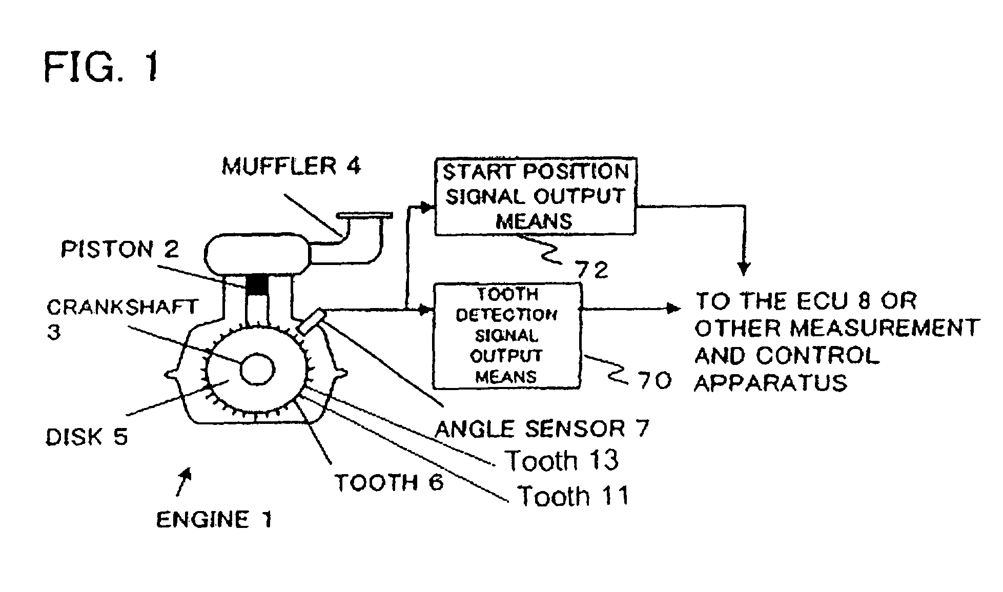
[0064]The tooth number / cycle output means 12 outputs a start position signal outputted by the start position signal output means 72, and, on the basis of a tooth detection signal outputted from the tooth detection signal output means 70, the tooth numbers of the teeth of the disk mounted on the crankshaft of the engine and the rotation cycle of the engine. Tooth numbers are assigned in sequence to teeth that have passed by the angle sensor 7, taking advantage of the fact that the start position signals are outputted after the ECU 8 has started measurement and control...


PUM

PropertyMeasurementUnit
rotationaaaaaaaaaa
timeaaaaaaaaaa
rotation timeaaaaaaaaaa

Abstract

A reference signal generator generating a reference signal for high-resolution measurement / control in real time includes a means for calculating the rotational trend, e.g. increase / decrease in the r.p.m., of an engine when a first tooth is detected by an angle sensor at the (n−1)-th cycle according to the mutual relation between the time interval between the first tooth and a second tooth just before the first tooth at the (n−1)-th cycle of the engine rotation and the time interval between the first tooth and a third tooth just after the first tooth, a rotation time predicting means for predicting the time interval between the first tooth and the third tooth at the n-th cycle by reflecting the rotational trend on the time interval between the first tooth and the second tooth at the n-th cycle, and a means for generating a reference signal by dividing a predicted time interval in correspondence with a predetermined angle resolution during the time after the first tooth is detected by the angle sensor at the n-th cycle till the third tooth is detected by the same.

Description

BACKGROUND OF THE INVENTION[0001]The present invention relates to a reference signal generator and method for measuring and controlling a rotating object.[0002]In recent years, an ECU (Electronic Control Unit) has been used for the purposes of measuring the output performance and controlling the fuel injection rate, injection and ignition timing and the like of an automobile internal combustion engine (hereinafter referred to as an “engine”). Examples of patent applications relating to a method and apparatus for controlling the operation of an engine include Japanese Laid-open Patent Application No. 53-65531, Japanese Patent Publication No. 7-33809, Japanese Patent No. 3262003.[0003]In an engine, the relationship between the output rotational speeds and strokes such as fuel injection, compression, combustion, and exhaust changes in accordance with the number of cylinders and the number of cycles. Therefore, these data are measured for each rotational angle of the crankshaft connecte...

Claims


Application Information

Patent Timeline
Patent Type & Authority Patents(United States)
IPC IPC(8): G01R25/00G01L3/26F02P5/00G06F17/40G01L3/00
CPCF02D41/009G01D5/2451Y02T10/84
Inventor SEKIMOTO, KOUJI
Owner A&D CO LTD
Why Eureka
Try Eureka