Suction baffle for scroll compressors

Inactive Publication Date: 2006-11-02
TECUMSEH PROD CO
View PDF18 Cites 19 Cited by
  • Summary
  • Abstract
  • Description
  • Claims
  • Application Information

AI Technical Summary

Benefits of technology

[0011] The present invention provides a scroll compressor including a hermetic housing with a motor-compressor unit disposed therein, including fixed and orbiting scrolls. The fixed scroll defines perpendicular axial and radial directions, and includes an outer wall having a suction inlet facing substantially in the radial direction. A baffle member is associated with the suction inlet of the fixed scroll, and in one embodiment, is attached to the fixed scroll with fasteners. The baffle member includes

Problems solved by technology

The turbulent flow of the working fluid within the upper portion of suction chamber 38 can potentially adversely effect the operating efficiency of compressor 10 by inhibiting uniform suction of working fluid into the suction inlet of the scrolls.
Additionally, the working fluid also tends to become heated, for example by the discharge gas above separator plate 18, if the working fluid circulates within the upper portion of the suction chamber before entering the suc

Method used


Image

  • Suction baffle for scroll compressors
  • Suction baffle for scroll compressors
  • Suction baffle for scroll compressors

Examples


Example

[0021] Corresponding reference characters indicate corresponding parts throughout the several views. The exemplification set out herein illustrates one preferred embodiment of the invention, in one form, and such exemplification is not to be construed as limiting the scope of the invention any manner.

DETAILED DESCRIPTION

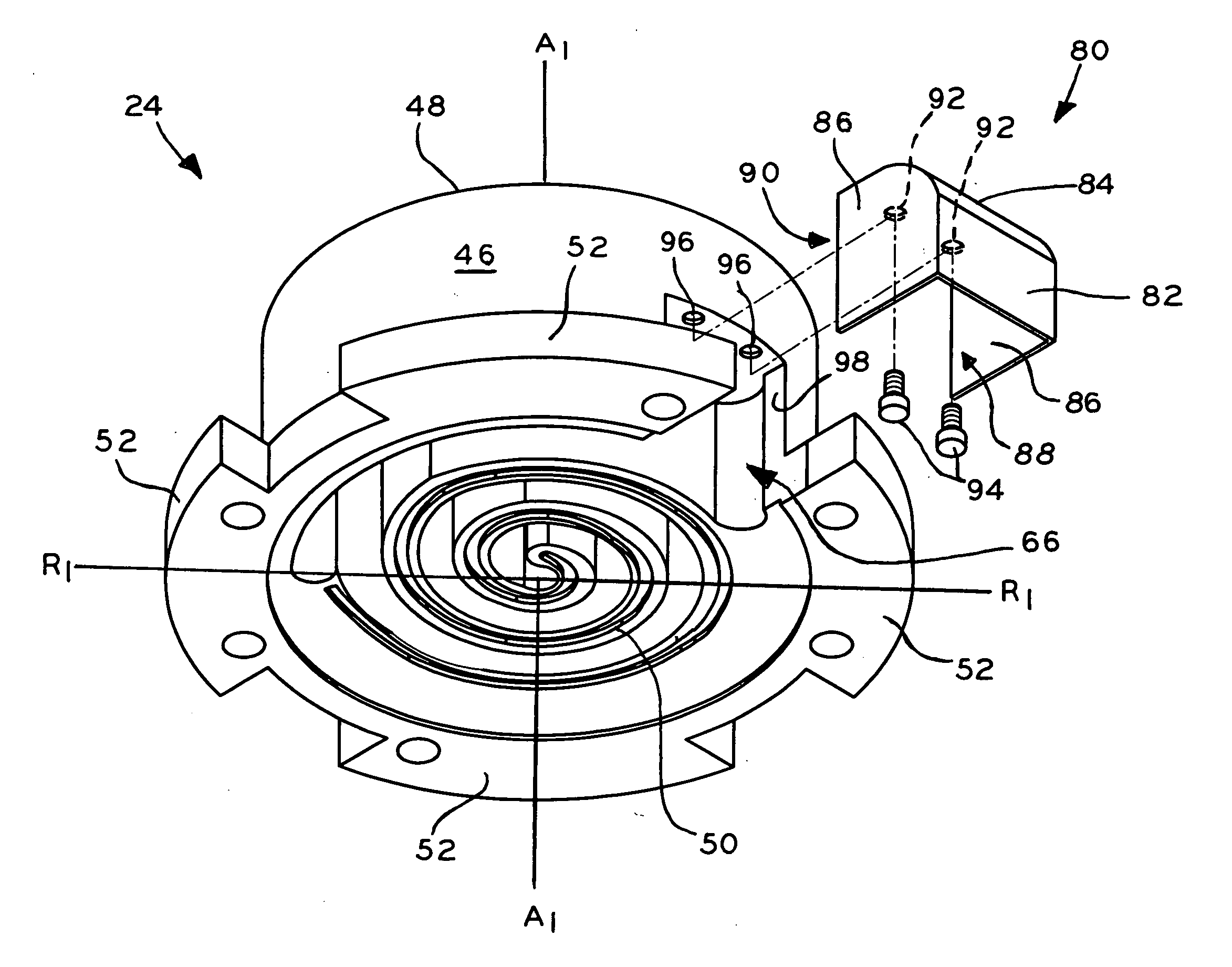
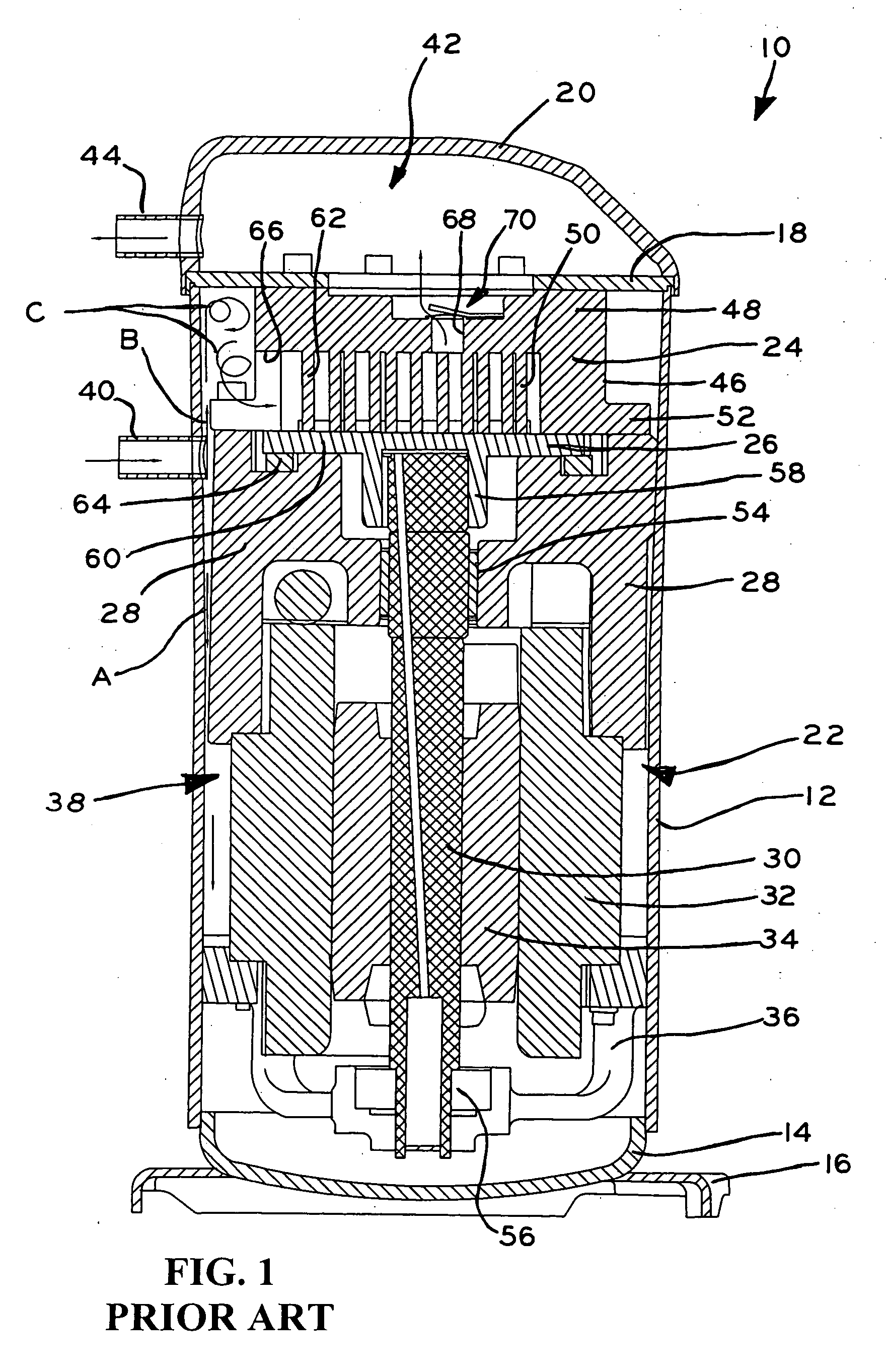
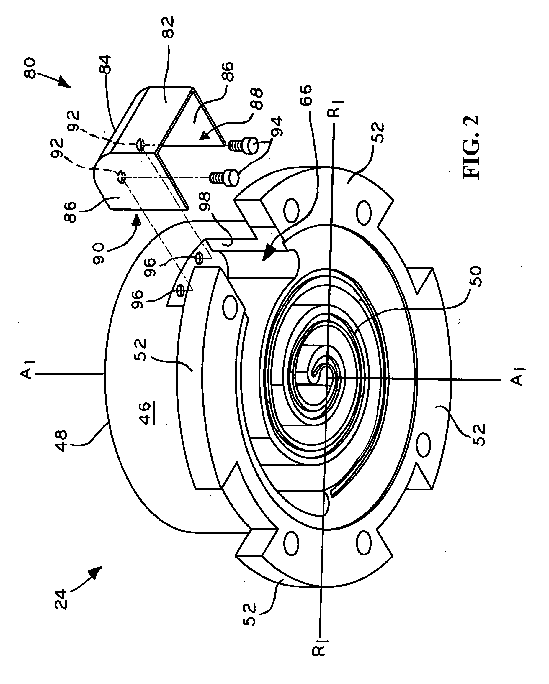
[0022] Referring to FIGS. 2-4, baffle member 80 according to the present invention is shown, which is associated with suction inlet 66 of fixed scroll 24 of scroll compressor 10. Except as described below, the components of scroll compressor 10 which are shown in FIGS. 2-4 are substantially identical to the components of scroll compressor 10 which are shown in FIG. 1, and the same reference numerals will be used to indicate identical or substantially identical components therebetween. Although scroll compressor 10 is shown disposed vertically in FIG. 4, baffle member 80 of the present invention is equally applicable in scroll compressors which are disposed horizont...


PUM


Abstract

A scroll compressor including a hermetic housing with a motor-compressor unit disposed therein, including fixed and orbiting scrolls. The fixed scroll defines perpendicular axial and radial directions, and includes an outer wall having a suction inlet facing substantially in the radial direction. A baffle member is associated with the suction inlet of the fixed scroll, and in one embodiment, is attached to the fixed scroll with fasteners. The baffle member includes a first open end facing in the axial direction toward a suction port of the compressor housing, and a second open end facing in the radial direction in fluid flow alignment with the suction inlet of the fixed scroll. The baffle member directs a portion of the working fluid which enters the compressor housing substantially directly into the suction inlet of the fixed scroll to reduce turbulent flow of the working fluid within the compressor housing, improving the operating efficiency of the compressor.

Description

BACKGROUND OF THE INVENTION [0001] 1. Field of the Invention. [0002] The present invention relates to scroll machines, and in particular, to the manner in which a working fluid is drawn into the variable volume working pockets which are defined between the fixed and orbiting scrolls of a scroll compressor. [0003] 2. Description of the Related Art. [0004] Referring to FIG. 1, a scroll compressor 10 is shown, which includes main housing 12, bottom cap 14 with base 16 secured to the lower end of housing 12, and a separator plate 18 and top cap 20 each secured to the upper end of housing 12 by a welding, brazing, or other suitable operation to define an enclosed hermetic housing in which the motor-compressor unit 22 of compressor 10 is disposed. Motor-compressor unit 22 generally includes a first, fixed scroll 24, a second, orbiting scroll 26, crankcase 28, drive shaft 30, stator 32, rotor 34, and outboard bearing assembly 36. Separator plate 18 is secured around its perimeter to the in...

Claims


Application Information

Patent Timeline
IPC IPC(8): F01C1/02F01C1/063F03C2/00F03C4/00F04C2/00F04C18/00
CPCF04C23/008F04C2250/101F04C29/12
Inventor GOPINATHAN, ANIL
Owner TECUMSEH PROD CO
Why Eureka
Try Eureka