
Resistance and noise reduction type insulator and high-speed train pantograph with same

A technology for high-speed trains and insulators, applied in the direction of insulators, circuits, current collectors, etc., can solve problems such as limited noise reduction effects, and achieve the effects of stable arrangement, reduced pulsating pressure, and simple structural manufacturing process

Pending Publication Date: 2022-05-27
NANJING UNIV OF SCI & TECH
View PDF0 Cites 0 Cited by
  • Summary
  • Abstract
  • Description
  • Claims
  • Application Information

AI Technical Summary

Problems solved by technology

At present, some scholars reduce the resistance during train running by adding a shroud to the pantograph, and some scholars reduce the noise during operation by adding zigzag stripes to the surface of the pantograph support rod, but these methods reduce the Therefore, it is urgent to improve the flow field characteristics and aerodynamic noise characteristics around the pantograph by optimizing the corresponding geometric structure, reduce the aerodynamic noise generated by the pantograph, and reduce noise pollution.

Method used


Image

  • Resistance and noise reduction type insulator and high-speed train pantograph with same
  • Resistance and noise reduction type insulator and high-speed train pantograph with same
  • Resistance and noise reduction type insulator and high-speed train pantograph with same

Examples


Embodiment 1

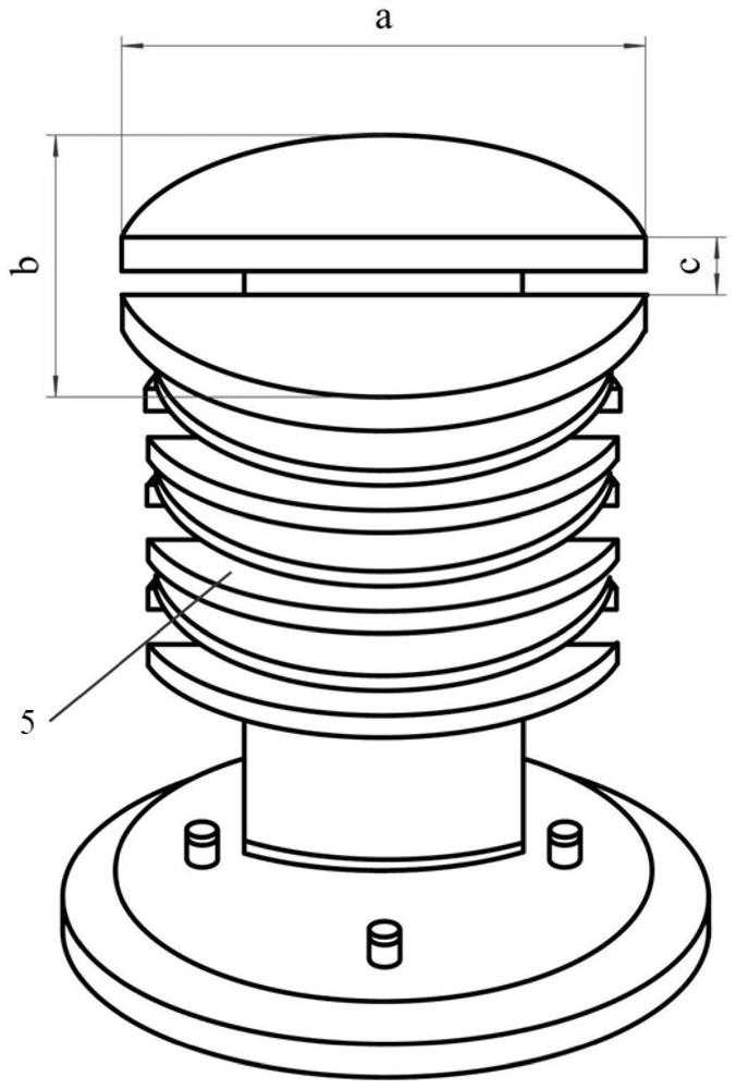
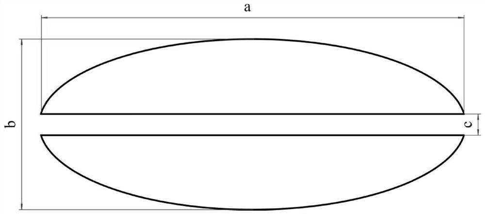
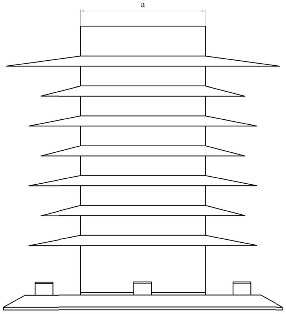
[0034] like Figure 1-4 As shown, a specific embodiment of the present invention is as follows: the ratio of the length of the long axis a to the short axis b of the elliptical cylinder section of the pantograph insulator 5 is 2, and the long axis facing the incoming flow direction is perpendicular to the incoming flow direction. for the short axis. The design width c of the central through hole is 10mm, which is symmetrically distributed along the central axis, and the through hole runs through the entire insulator 5 .

Embodiment 2

[0036] A specific embodiment of the present invention is: the ratio of the length of the long axis a to the short axis b of the elliptical cylinder section of the pantograph insulator 5 is 2.5, the long axis facing the incoming flow direction, and the short axis perpendicular to the incoming flow direction . The design width c of the central through hole is 12.5 mm, which is symmetrically distributed along the central axis, and the through hole runs through the entire insulator 5 .

Embodiment 3

[0038] A specific embodiment of the present invention is as follows: the ratio of the long axis a to the short axis length b of the elliptical cylinder section of the pantograph insulator 5 is 3, the long axis facing the incoming flow direction, and the short axis perpendicular to the incoming flow direction . The design width c of the central through hole is 15 mm, which is symmetrically distributed along the central axis, and the through hole runs through the entire insulator 5 .


PUM


Abstract

The invention discloses a resistance and noise reduction type insulator and a high-speed train pantograph with the same, the insulator is located at the bottom of the pantograph, and a mounting underframe of the pantograph and a train roof are assembled together; the insulator has an elliptical cylindrical cross section, a long axis facing the incoming flow direction, and a short axis perpendicular to the incoming flow direction. The pantograph insulator adopts a centered through hole design, and centered through holes are symmetrically distributed along the central axis and penetrate through the whole insulator; the pantograph mainly comprises a carbon slide plate, a pantograph corner, a support rod, an upper arm, an insulator and the like, the carbon slide plate adopts a rectangular cross section design, and four edges on two sides of a windward side and a leeward side of the rectangular cross section adopt a fillet design. According to the invention, the pulsating pressure on the surface of the pantograph can be effectively reduced, the aerodynamic resistance and noise generated by the whole pantograph are obviously reduced, the original structure of the pantograph is reserved to the greatest extent, and the related structure is simple to manufacture and easy to realize.

Description

technical field [0001] The invention belongs to the technical field of electrified railway locomotives, and particularly relates to a drag-reducing and noise-reducing insulator and a high-speed train pantograph with the same. Background technique [0002] With the rapid improvement of high-speed train-related technologies, the convenience, speed, comfort and safety of high-speed trains attract more and more passengers to choose high-speed trains as a travel tool. However, with the gradual increase of the running speed of high-speed trains, the aerodynamic noise problem caused by this has gradually become a major problem that cannot be ignored in the process of train operation. The noise generated by high-speed trains during operation is mainly divided into three categories: electrical noise, wheel-rail noise and aerodynamic noise. Aerodynamic noise is caused by the interaction of various components and air on the shape of the high-speed train during the operation of the hig...

Claims


Application Information

Patent Timeline
IPC IPC(8): H01B17/38B60L5/20
CPCH01B17/38B60L5/205B60L5/20Y02T30/00
Inventor 周毅韩斐胡常莉
Owner NANJING UNIV OF SCI & TECH
Learn More