Layered support sheet for high-yield spot cutting from gels or membranes

Inactive Publication Date: 2006-11-02
BIO RAD LAB INC
View PDF11 Cites 7 Cited by
  • Summary
  • Abstract
  • Description
  • Claims
  • Application Information

AI Technical Summary

Benefits of technology

[0008] It has now been discovered that these problems and others in connection with spot cutting can be reduced or eliminated by using a support surface covered with a thin, relatively soft, layer, i.e., one that is softer (more pliable) than the underlying support surface, on the side facing the gel or membrane. This intermediate layer is not part of the gel or membrane and is sufficiently pliable to compensate for any irregularity in, or misalignment of, the cutting edge of the cutting tool relative to the gel or membrane. The tool is thus lowered against the gel or membrane and pressed with sufficient force to penetrate the gel or membrane without penetrating the intermediate layer, thereby fully excising the spot in the form of

Problems solved by technology

A risk in this operation is that the cutting of the spot may be incomplete, thereby preventing the spot from being fully liberated from the remainder of the gel or membrane.
A lack of perpendicularity can also cause a partially cut piece to be pulled out of the cylinder tip as the cutting tool is being lifted away.
Even if full separation is achieved, a

Method used


Image

  • Layered support sheet for high-yield spot cutting from gels or membranes
  • Layered support sheet for high-yield spot cutting from gels or membranes

Examples


Embodiment Construction

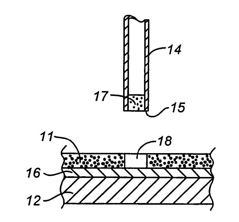
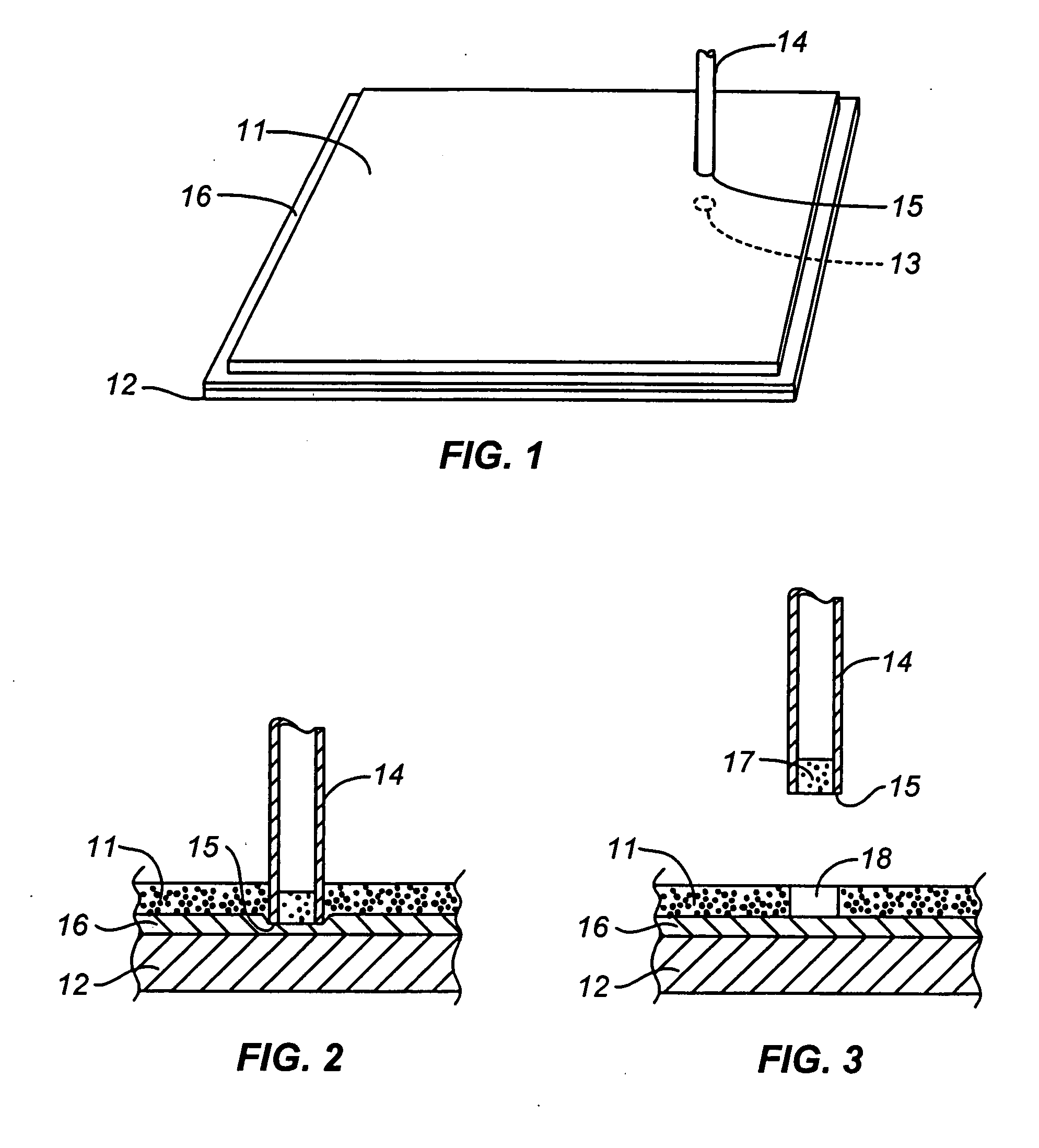
[0012] The term “sheet-form matrix” is used in this specification and the appended claims as a generic term to denote the medium in which the sample array resides. Gels and membranes are both encompassed by the term. The “cylinder” cited in this specification and the appended claims is any body formed by a line tracing a closed curve. The closed curve may thus for example be a square, a rectangle, or other polygon, or an ellipse or a circle. Circles and hence circular cylinders are preferred.

[0013] The support surface can be formed of any conventional material that is commonly used in laboratory equipment and in parts and components for laboratory instrumentation. By “rigid surface” is meant a surface having sufficient rigidity to support the sheet-form matrix, whether it be a gel or a membrane, in a substantially flat configuration. The rigid surface can therefore be the surface of a sheet that is moderately flexible. A convenient material for the support surface is a polymer such...


PUM

PropertyMeasurementUnit
Thicknessaaaaaaaaaa
Thicknessaaaaaaaaaa
Thicknessaaaaaaaaaa

Abstract

The excision of sample spots from a gel or membrane by pressing a cutting tool terminating in a hollow cylinder against the gel or membrane supported on a rigid surface is made more reliable by interposing a relatively pliable, intermediate layer on the side of the surface facing the gel or membrane. The pliability of the intermediate layer compensates for any irregularity or misalignment of the cutting edge of the cylinder relative to the gel or membrane.

Description

CROSS-REFERENCE TO RELATED APPLICATION [0001] This application claims benefit from U.S. Provisional Patent Application No. 60 / 669,453, filed Apr. 7, 2005, the contents of which are incorporated herein by reference in their entirety.BACKGROUND OF THE INVENTION [0002] 1. Field of the Invention [0003] This invention resides in the field of biochemical laboratory equipment, and particularly equipment that is used for analyses of multitudes of small samples of biologically derived materials. [0004] 2. Description of the Prior Art [0005] Many biochemical laboratories perform procedures that involve analyses of large numbers of samples, each containing biological species that are very similar in structure and each available only in very small quantities. Analyses of this kind are performed in a sequence of stages, each stage requiring close control of the reaction conditions while maintaining individual handling of each sample. To accomplish this, the samples are often arranged in two-dime...

Claims


Application Information

Patent Timeline
IPC IPC(8): C12Q1/00G06K1/00
CPCG01N2001/288G01N1/286
Inventor THORNTON, KEVINGORDON-GILMORE, RANDYMCEACHERN, DAN
Owner BIO RAD LAB INC
Why Eureka
Try Eureka