Threaded rod and nut assembly

a technology of threaded rods and nuts, which is applied in the direction of intravenous devices, medical syringes, infusion syringes, etc., can solve the problem of nuts jamming

Inactive Publication Date: 2006-11-02
NOVO NORDISK AS
View PDF6 Cites 171 Cited by
  • Summary
  • Abstract
  • Description
  • Claims
  • Application Information

AI Technical Summary

Benefits of technology

[0004] The present invention provides for a threaded rod and nut assembly having a stop means that prevents the nut from being screwed off the piston rod, at least in one direction. And it further provides for a method of making a nut and threaded rod assembly having a stop means. In one embodiment, a portion of a rod is threaded. Near a proximal end of the rod, the thread ends (preferably abruptly), and beyond that (in a proximal direction) there is a cylindrical surface having the same (or smaller) outside diameter as the largest diameter of the threaded portion. A groove or a plurality of grooves are machined longitudinally in the rod. A nut is t

Problems solved by technology

However, when large torque loads are exerted

Method used


Image

  • Threaded rod and nut assembly
  • Threaded rod and nut assembly

Examples


Embodiment Construction

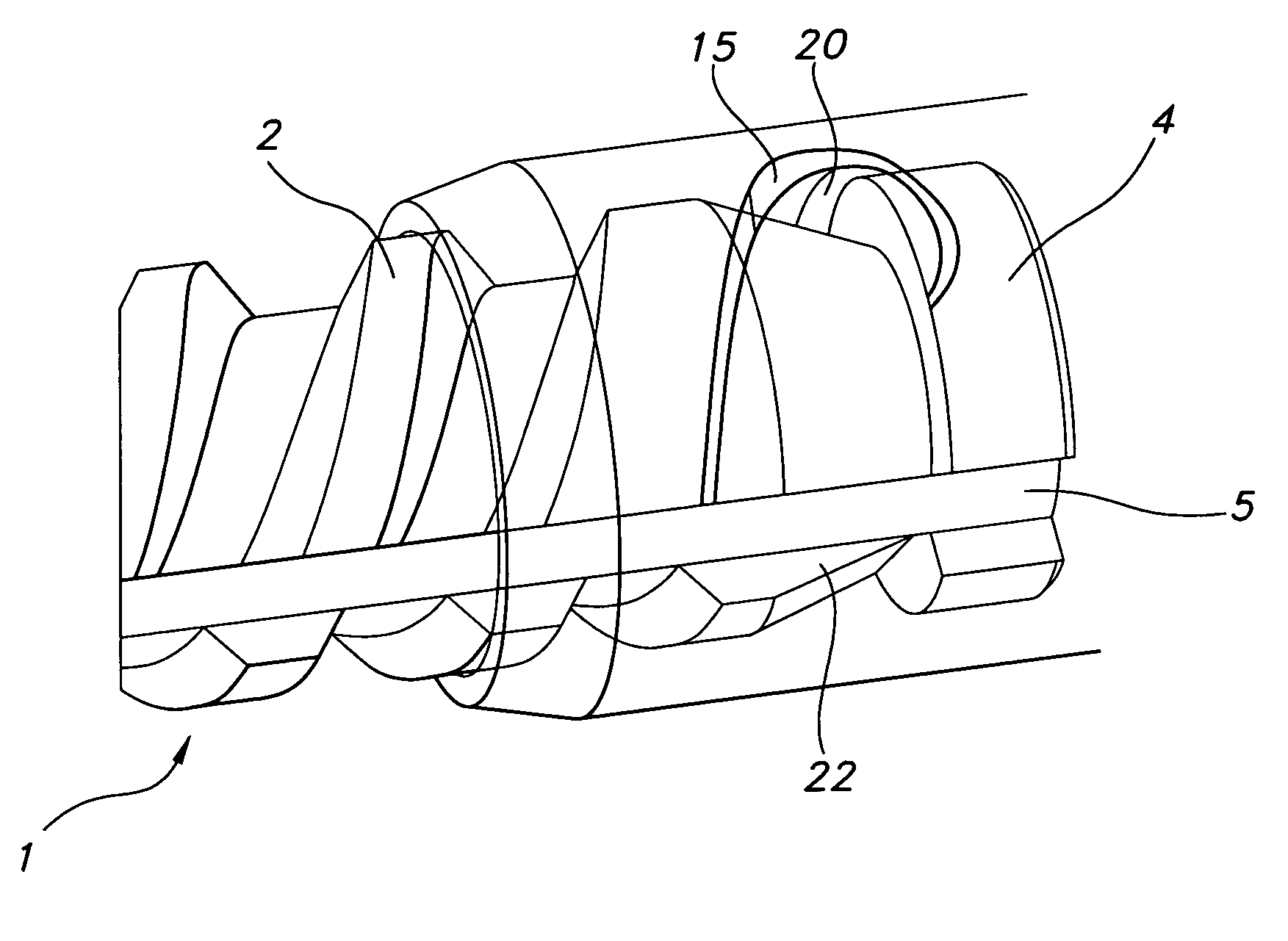
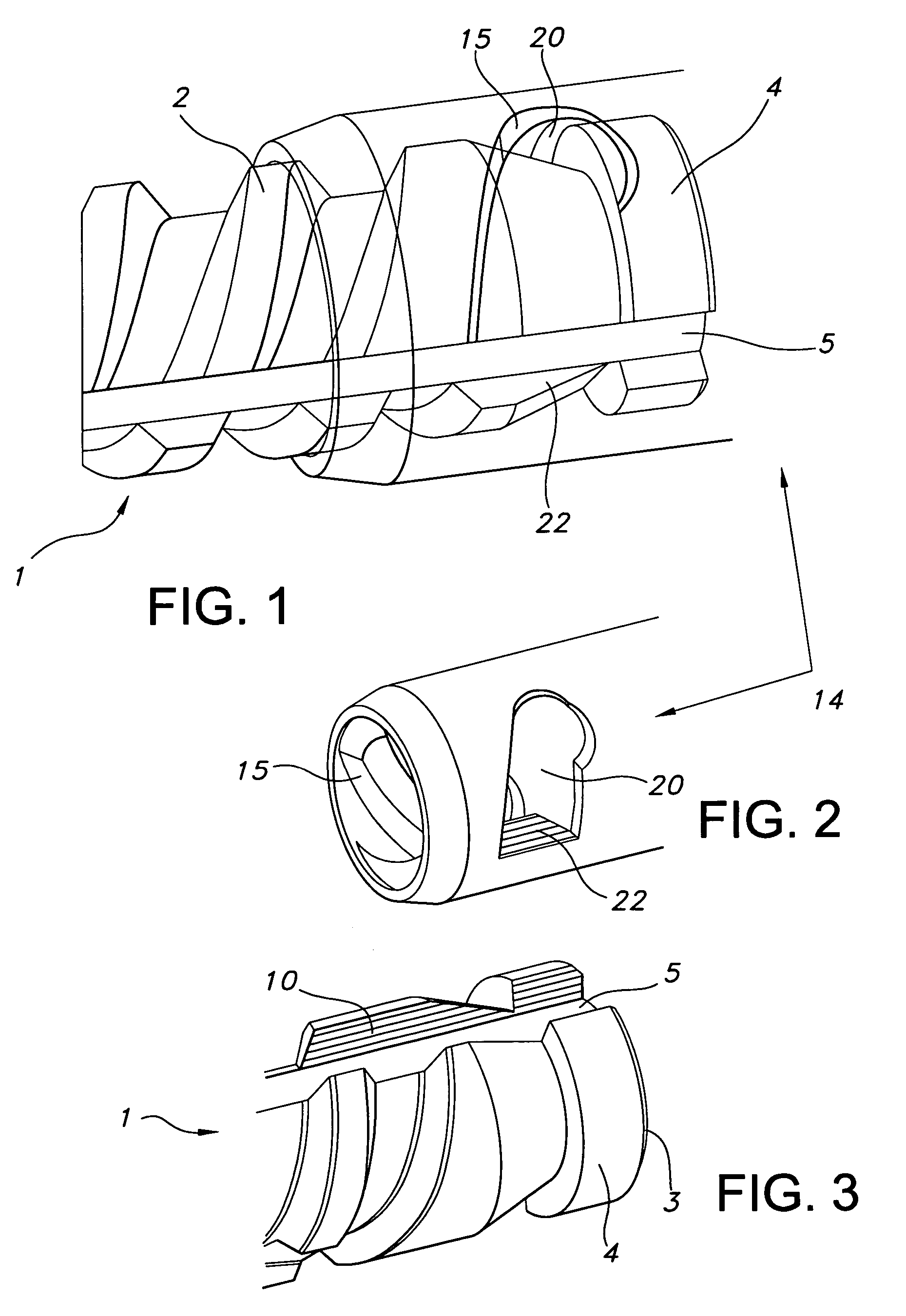
[0014] As is shown in FIG. 1, a rod 1, such as a piston rod for an injection device, is threaded with male threads 2. The threads 2 end prior to the end 3 of the rod 1, thereby leaving a cylindrical portion 4 that is unthreaded. One or more grooves 5 are machined into the rod 1 and run in a longitudinal direction. As shown in FIG. 3, the groove 5 cuts across the threads 2 and the cylindrical portion 4. This results in a stop surface 10 being formed on the cylindrical portion 4. Preferably the threads are cut with a cutting tool that is abruptly removed from the rod so that the thread ends abruptly. Moreover, the outer diameter of the cylindrical portion is preferably less than or equal to the maximum outer diameter of the threaded portion. The order of steps is not critical as long as the steps result in the above described structure. For example, the rod may be grooved or flat surfaces cut into it, before it is threaded. Of course, other methods besides cutting may be employed to c...


PUM


Abstract

Disclosed is a stop for preventing a threaded rod from screwing thru a nut. The stop is formed by manufacturing a threaded rod having an unthreaded cylindrical portion and one or more grooves cut or manufactured longitudinally in the rod across both the threaded section and the unthreaded portion. A nut having an interior thread complementary to that of the rod has a hole bored thru its wall over a peak in the interior thread. The hole creates a stop surface on the interior thread that abuts a stop surface created by the groove in the unthreaded portion of the rod.

Description

FIELD OF THE INVENTION [0001] The present invention relates to threaded rod and nut assemblies. In particular it relates to a stop means for preventing relative movement of the rod with respect to the nut. This is particularly relevant for injection devices, such as pen style syringes, which often use threaded piston rods and nuts to drive preset doses from the syringe. DESCRIPTION OF RELATED ART [0002] A typical injection device comprises a threaded piston rod and a nut. Usually, the piston rod has a groove or grooves machined so that it has a not round cross-section. In general, two types of devices are common. In one type, a drive nut is coupled to a drive means that spins the drive nut, which is rotatable but is fixed in the housing to prevent longitudinal movement. An end-of-content mechanism for such device is disclosed in U.S. Pat. No. 6,582,404. In other devices, the nut is screwed along the piston rod during a dose setting operation. See e.g. US Patent Application Nos. 2002...

Claims


Application Information

Patent Timeline
IPC IPC(8): A61M5/315
CPCA61M5/31501A61M5/31511A61M2005/31508A61M5/31541A61M5/3155A61M5/31515
Inventor PEDERSEN, THOMASRASMUSSEN, HENRIK
Owner NOVO NORDISK AS
Why Eureka
Try Eureka