System and method for synchronized phasor measurement

a phasor and synchronization technology, applied in the field of electric power transmission networks, can solve the problems of magnitude, cross coupling error, and magnitude error in estimated phase angle generation of cross coupling errors

Active Publication Date: 2006-11-02
GENERAL ELECTRIC CO
View PDF5 Cites 101 Cited by
  • Summary
  • Abstract
  • Description
  • Claims
  • Application Information

AI Technical Summary

Problems solved by technology

Thus, Fourier-like algorithms derived from signal models that assume amplitude, frequency and phase angle to be constant for computing synchronized phase measurements, provide erroneous results as the assumptions are violated during transient conditions.
Changes in amplitude, frequency, or phase angle generate cross coupling errors.
For example, a change in phase angle creates an error in estimated magnitude, and a change in magnitude creates an error in estimated phase angles.
Hence, present methods for computing synchronized phase measurements have limitations for achieving high levels of accuracy during the transient conditions.

Method used


Image

  • System and method for synchronized phasor measurement
  • System and method for synchronized phasor measurement
  • System and method for synchronized phasor measurement

Examples


Embodiment Construction

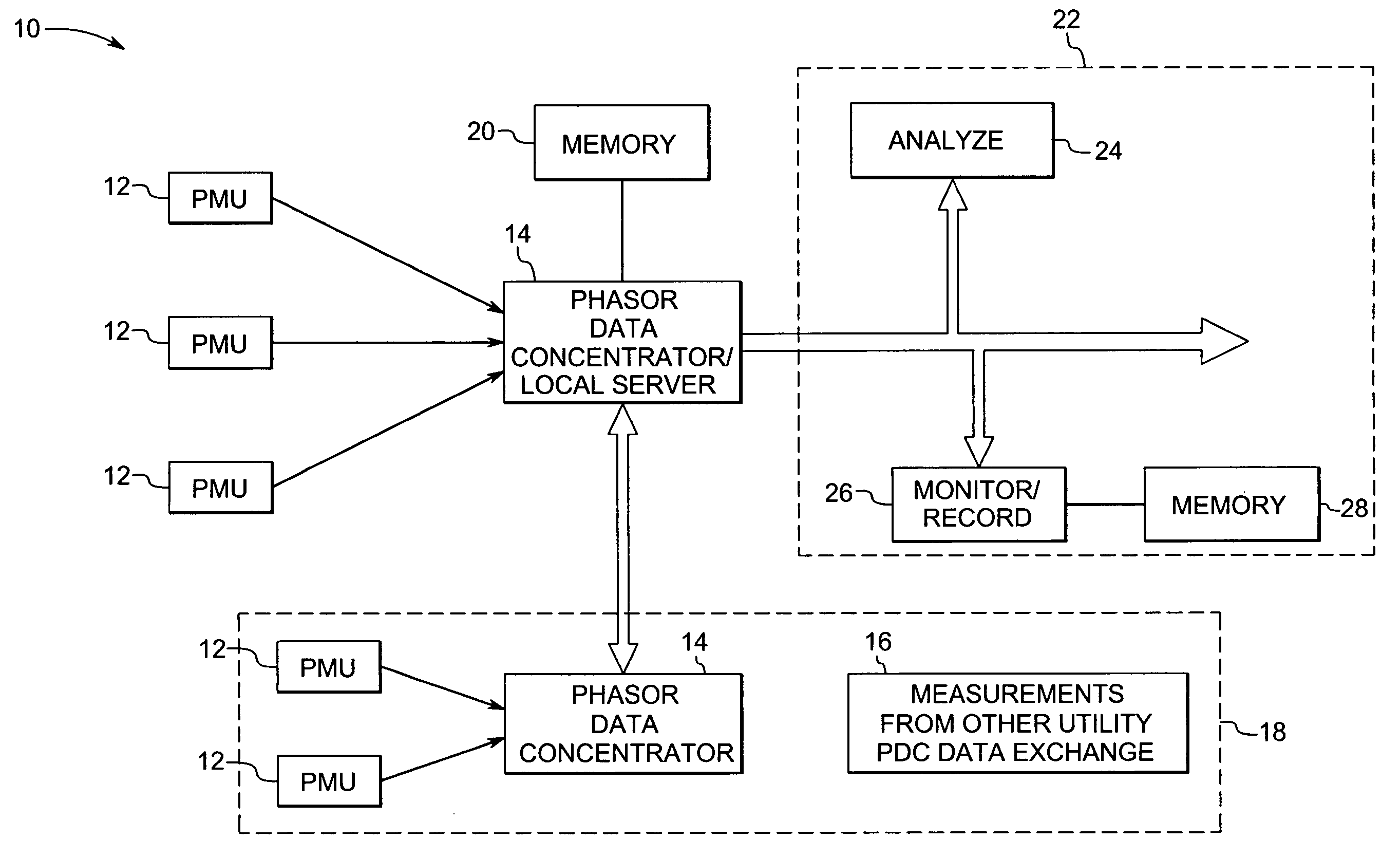
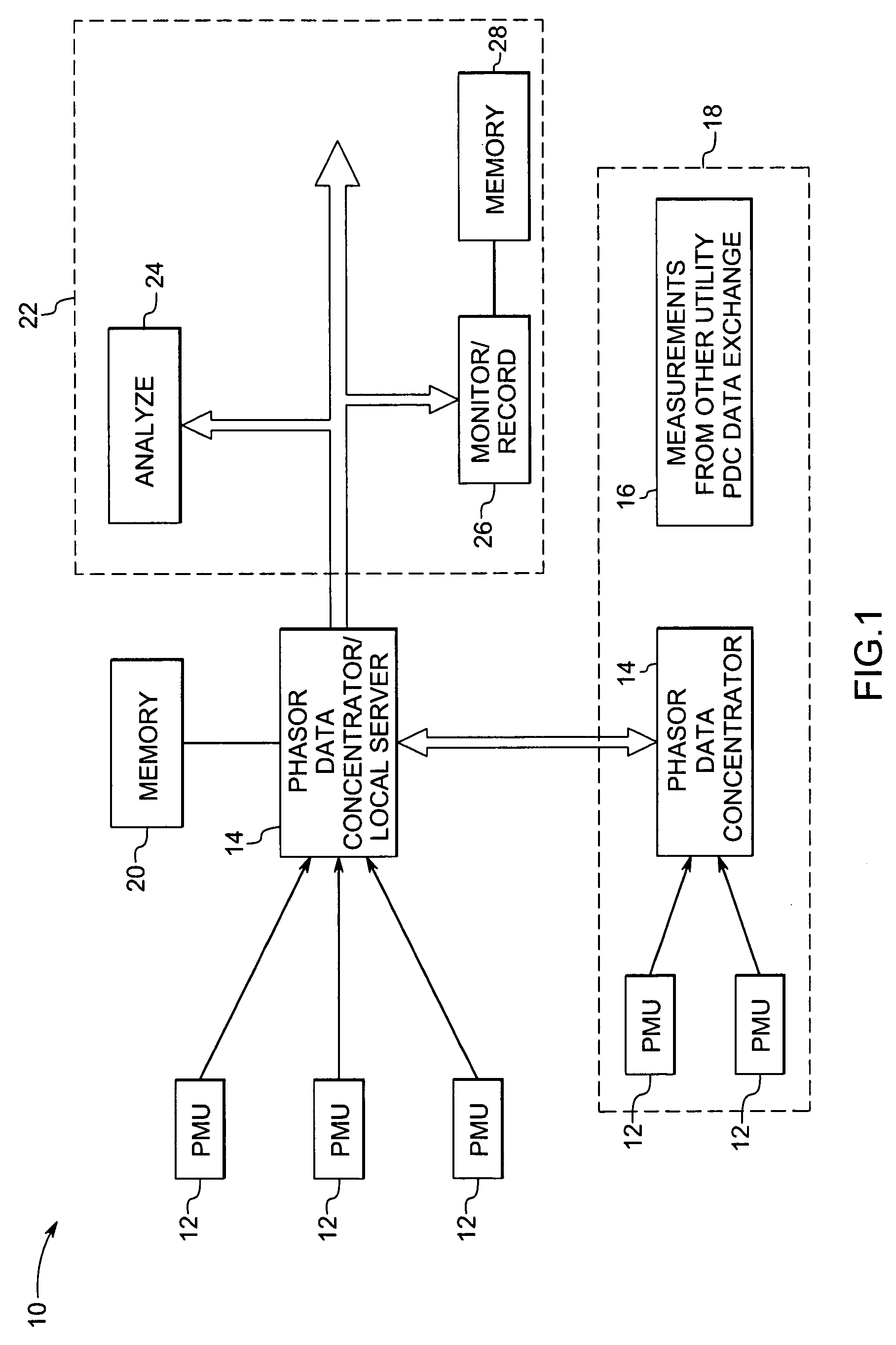
[0014]FIG. 1 is a block diagram of a phasor measurement system 10 implemented according to one aspect of the invention. The phasor measurement system 10 includes one or more phasor measurement units (PMUs) 12 placed at different locations or substations, for providing synchronized phasor measurement data of voltage, current and frequency, according to aspects of the present technique. In one embodiment, synchronized phasor measurement data may be provided in real time. The synchronized phasor measurement data or synchrophasors from various phasor measurement units 12 are then communicated to a phasor data concentrator (PDC) 14 or a dedicated local server at the control center. In one embodiment, the PMUs 12 may record synchrophasors locally and may then upload it to PDC 14 in batches. The PMU 12 uploads its time stamped phasor data using communication medium such as dedicated telephone line or fiber optic link or through the wide area network (WAN). It should be noted that the phaso...


PUM


Abstract

A phasor measurement system is provided for computing synchronized phasor measurements. The phasor measurement system includes acquisition circuitry for acquiring voltage or current values from a power line, sampling circuitry for sampling the voltage or current values, and processing circuitry for computing a phasor and at least one time derivative of the phasor based on the sampled voltage or current values and for computing a synchronized phasor value based on the phasor and the at least one time derivative of the phasor.

Description

BACKGROUND [0001] The invention relates generally to the field of electrical power transmission networks and in particular to a technique for synchronized phasor measurement based on multi-parameter model of the fundamental frequency component of the signal. [0002] The application of synchronized phasor measurements of voltages and currents from widely dispersed locations in an electrical power transmission network is well recognized for monitoring, operation and control of the power system network. Traditionally, power systems may be monitored through a combination of non-synchronized measurements, power flows and voltage magnitudes, feeding into a software model of the network which using other parameters of the network, calculates the balance of quantities. These quantities may however be calculated directly using synchronized phasor measurements (that is, phasor measurements with reference to absolute time). The phasor measurement unit (PMU) is considered to be one of the import...

Claims


Application Information

Patent Timeline
Patent Type & Authority Applications(United States)
IPC IPC(8): G01R19/00
CPCG01R19/2513Y04S10/265Y02E60/728Y02E40/70Y02E60/00Y04S10/00Y04S10/22
Inventor PREMERLANI, WILLIAM JAMESKASZTENNY, BOGDAN ZDZISLAWADAMIAK, MARK GERARD
Owner GENERAL ELECTRIC CO
Why Eureka
Try Eureka