Stator turn fault detection apparatus and method for induction machine

a technology of induction machine and turn fault, which is applied in the direction of special data processing applications, dynamo-electric motor/converter starters, emergency protective arrangements for automatic disconnection, etc., can solve the problems of false results of algorithm and affect the accuracy and precision of measuring equipmen

Active Publication Date: 2010-08-05
GENERAL ELECTRIC CO
View PDF18 Cites 40 Cited by
  • Summary
  • Abstract
  • Description
  • Claims
  • Application Information

AI Technical Summary

Benefits of technology

[0006]Another method improving an algorithm for determining turn faults in a stator of a motor is provided. The method includes tuning the negative sequence impedance depending on the temperature measuring a temperature of the motor, modifying the negative sequence impedance based on the temperature, and determining a parameter indicative of the number of turn faults in the stator based on the negative sequence impedance.

Problems solved by technology

Variation in the instruments, such as gain and phase delays, may result in erroneous measurements that lead to false results from the algorithm.
Additionally, changes in environmental conditions may also affect the accuracy and precision of the measuring equipment.

Method used


Image

  • Stator turn fault detection apparatus and method for induction machine
  • Stator turn fault detection apparatus and method for induction machine
  • Stator turn fault detection apparatus and method for induction machine

Examples


Embodiment Construction

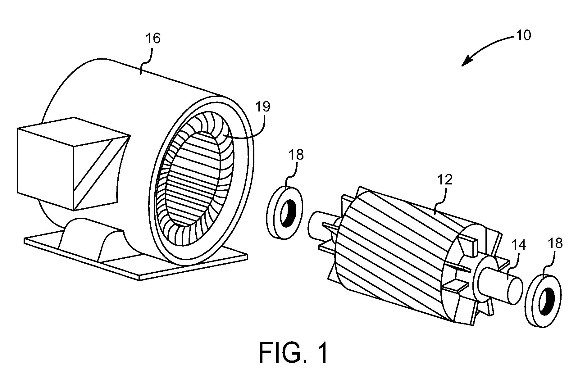
[0015]FIG. 1 is a diagrammatical perspective illustration of an induction motor 10. FIG. 1 is provided for illustrative purposes only, and embodiments of the present invention are not limited to any specific induction motor or configuration thereof. In the illustrated example, the motor 10 includes a rotor assembly 12, which includes a rotor shaft 14 extending through a rotor core. The rotor assembly 12 along with the shaft 14 can rotate inside the stator assembly 16 in a clockwise or a counter-clockwise direction. Bearing assemblies 18 that surround the rotor shaft 14 may facilitate such rotation within the stator assembly 16. The stator assembly 16 includes a plurality of stator windings 19 that extend circumferentially around and axially along the rotor shaft 14 through the stator assembly 16. During operation, a rotating magnetic field induced in the stator windings 19 reacts with the induced current in the rotor assembly 12 to cause the rotor assembly 12 to rotate, converting e...


PUM


Abstract

A system and method are provided for correction of parameters used in determination of stator turn faults of an induction motor. An embodiment may include determining a residual impedance and/or a residual voltage of the motor, and correcting a normalized cross-coupled impedance based on the residual impedance and residual voltage. Additional embodiments may include measuring an operating temperature of the motor and determining a negative sequence impedance of the motor based on the temperature. Another embodiment may include measuring voltages and currents of the motor and determining phasors for the voltages and currents using compensation for variations from a nominal frequency of the motor.

Description

BACKGROUND[0001]The invention relates generally to detecting turn faults in the stator of alternating current (AC) induction motors.[0002]AC induction motors are used in a wide array of applications and processes. An AC induction motor typically includes a stationary portion, a “stator,” and a rotating portion, a “rotor.” In a 3-phase AC motor, power is applied to the stator to induce a magnetic field, causing the rotor to turn and generate mechanical energy. The stator may include any number of “windings,” or wound poles that carry the current necessary to induce the magnetic field. These windings may also be characterized by the “turns” in the winding.[0003]In many environments, the windings in the stator are subject to shorts between the turns of the windings, commonly referred to as “turn faults.” In operating such motors, various algorithms may be used to determine the state of the motor. For example, an algorithm may be used to determine the number of turn faults. The paramete...

Claims


Application Information

Patent Timeline
Patent Type & Authority Applications(United States)
IPC IPC(8): H02H7/08
CPCG01R31/025G01R31/346G01R31/34G01R31/52
Inventor KASZTENNY, BOGDAN Z.R., SOMAKUMARTIWARI, ARVIND KUMARBANERJEE, ARIJIT
Owner GENERAL ELECTRIC CO
Why Eureka
Try Eureka