Cylinder head seal

a technology of cylinder head and seal, applied in the direction of engine seal, engine components, sealing arrangements, etc., can solve the problems of deformation of the sealing surface, unsatisfactory measures, and increased manufacturing costs, and achieve the effect of less rigidity

Inactive Publication Date: 2006-11-09
FEDERAL MOGUL SEALING SYST
View PDF28 Cites 2 Cited by
  • Summary
  • Abstract
  • Description
  • Claims
  • Application Information

AI Technical Summary

Benefits of technology

[0013] Through distribution of the beads, decrease of the bead height, or bead side leg flattening, the beads are engineered with less rigidity.
[0014] By reduction of the width, increase of the bead height, or use of a steeper bead side leg, the bead is made more rigid.
[0016] In such manner, beads adjusted to the particular conditions of operation lead to a uniform pressure around the passage opening and, respectively, the combustion chamber passage opening and thus use less of the available screw strength. This in turn has a positive influence on the durability of the seal connection and leads to a minor distortion of the contiguous walls.

Problems solved by technology

The different rigidities of the flanges and the finite number of screws naturally leads to deformation of the sealing surface.
The corresponding prior art seals adjust themselves to undesirable sealing pressures, but the manufacturing cost is elevated.
Such measures are undesirable since the seal system must always be constructed with the weakest member in mind.

Method used


Image

  • Cylinder head seal
  • Cylinder head seal
  • Cylinder head seal

Examples


Embodiment Construction

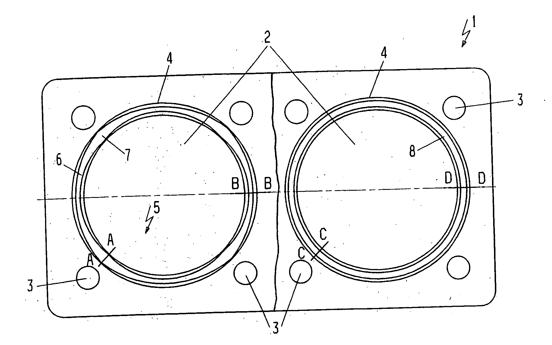
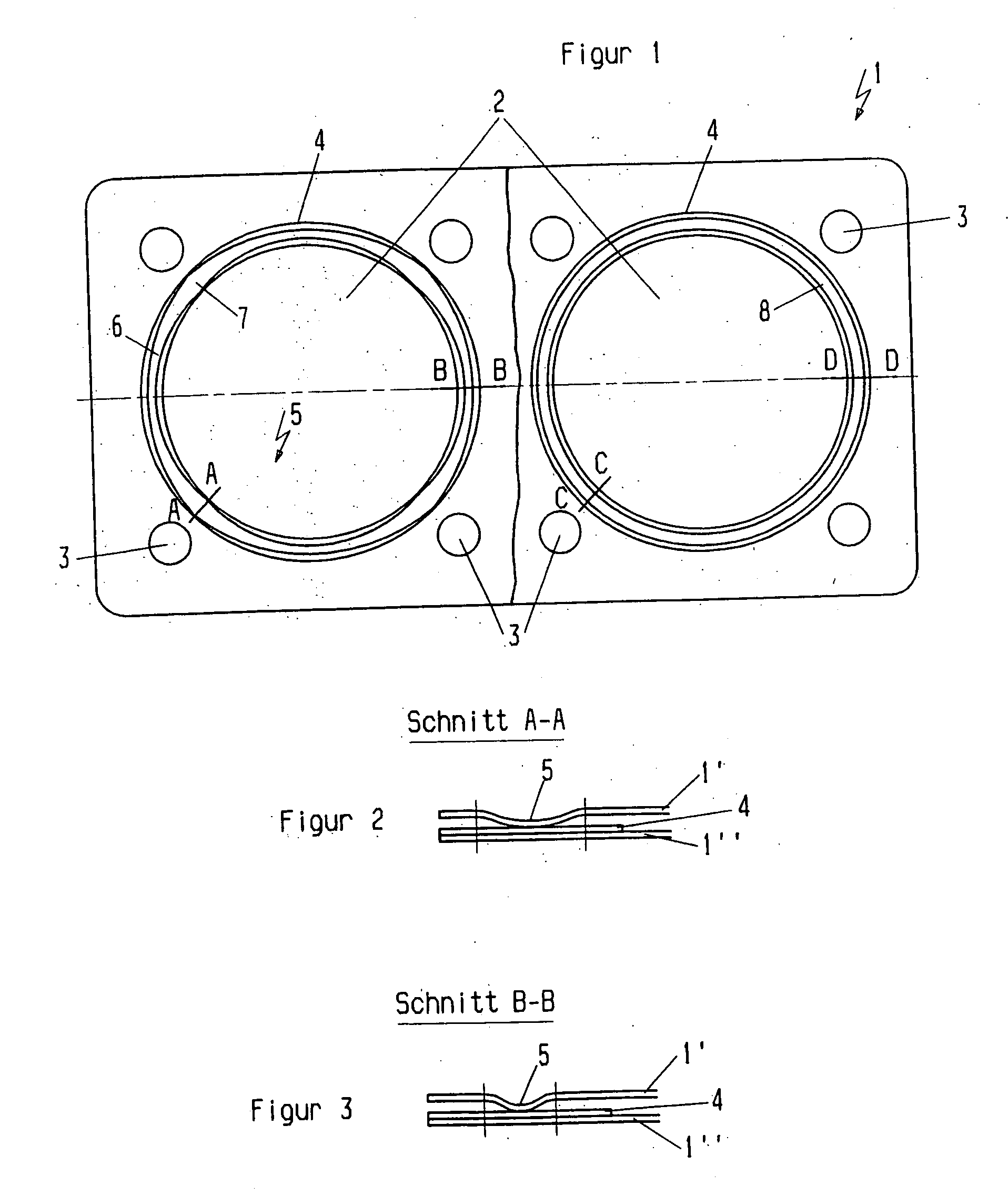
[0020]FIG. 1 shows in the top view as a cylinder head seal for an internal combustion engine an insertable multi-layered seal 1, containing several combustion chamber passage opening component passage openings 2 as well as equivalent surrounding screw punch holes 3. In the left section of the flat seal it is recognizable that a support ring 4 is provided, upon which a bead 5 of another layer is overlaid, wherein the bead 5 contains areas 6,7 of different width.

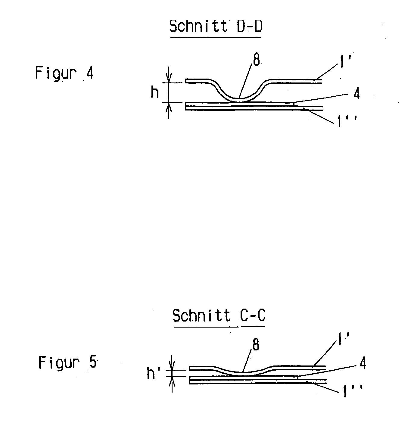
[0021] In the right section of FIG. 1 a support ring 4 is likewise provided, upon which a bead 8 is overlaid, which has equal broad portions in the circumferential direction, but different heights (not shown here).

[0022]FIGS. 2 and 3 show sections through the left part of flat seal 1. Recognizable are two layers 1″, 1″ as well as the support ring 4. The section according to line A-A through FIG. 1 shows an area in which the bead 5 is shaped more broadly 7 than as is the case with the section corresponding to line B-B. By thi...


PUM


Abstract

Multi-layered flat seal, in particular a cylinder head seal for an internal combustion engine, with a first layer having at least a passage opening as well as several screw passage punch holes, at least a support ring surrounding the passage opening, and at least a second layer, which at least is provided with a bead of partially circular form, whereby the bead interacts cooperatively with the support ring and, viewed in circumferential direction, is formed by mechanical shaping with areas of different spring stiffness.

Description

RELATED APPLICATIONS [0001] This application claims priority to German Patent Application No. 10 2005 020 923.8, filed May 4, 2005. BACKGROUND OF THE INVENTION [0002] 1. Technical Field [0003] This invention relates to a multi-layered seal, in particular a cylinder head seal for an internal combustion engine. [0004] 2. Related Art [0005] A metallic flat seal, in particular a cylinder head seal, has become known through U.S. Pat. No. 5,628,518, which has several layers and with which at least one support ring can be introduced around the combustion chamber passage opening. The layers of the cylinder head seal are provided with beads, whereby the beads interact co-operatively with the support ring. The beads are formed here of uniform cross-section in the circumferential direction. [0006] EP-B 0 306 766 is taken from a similar flat seal of the aforementioned US patent, in which the support ring can exhibit different cross-sectional forms. [0007] In EP-A 0 863 335 a metallic flat seal,...

Claims


Application Information

Patent Timeline
Patent Type & Authority Applications(United States)
IPC IPC(8): F02F11/00
CPCF02F11/002F16J2015/085F16J15/0825
Inventor HILGERT, CHRISTOPH
Owner FEDERAL MOGUL SEALING SYST
Why Eureka
Try Eureka