Joint structure for independent suspension

a joint structure and independent technology, applied in the direction of bicycles, transportation and packaging, motorcycles, etc., can solve the problems of increased lateral widthwise distance, excessive joint angle, and difficult to ensure, so as to reduce the number of components and reduce the lateral width , the effect of simplifying assembly

Active Publication Date: 2007-04-05
HONDA MOTOR CO LTD
View PDF12 Cites 0 Cited by
  • Summary
  • Abstract
  • Description
  • Claims
  • Application Information

AI Technical Summary

Benefits of technology

[0010] According to the first aspect of the present invention, the intervention of a cylindrical member can be eliminated by directly coupling the outer races together. Therefore, a lateral width can be reduced according to the elimination. Furthermore, the number of component parts can be reduced.
[0011] According to the second aspect of the present invention, the left-hand and right-hand joint-part shafts are formed such that one is a male member and the other is a female member and are coupled to each other through fitting. Therefore, assembly can be simplified and the left-hand and right-hand outer races can be securely coupled to each other.
[0012] According to the third aspect of the present invention, members that hold the driven sprocket and brake disk are different from each other; therefore, the driven sprocket supporting part's deformation resulting from a chain's tensile force has no effect on the brake disk. Thus, the parts for supporting the driven sprocket and brake disk each need less rigidity. This can reduce the weight of the joints.

Problems solved by technology

The structure for coupling the left-hand and right-hand outer races via the above-mentioned tubular member has a problem in that it is difficult to ensure a necessary wheel stroke because of the following: Since the left-hand and right-hand outer races are independently coupled to the tubular member, a lateral widthwise distance is increased according to the intervention of the tubular member, which may provide an excessive joint angle in a limited tread.
Therefore, there arises a problem in that it is difficult to ensure a necessary wheel stroke.

Method used


Image

  • Joint structure for independent suspension
  • Joint structure for independent suspension
  • Joint structure for independent suspension

Examples


Embodiment Construction

[0021] Embodiments of the present invention will below be described with reference to the drawings. Note that the directions such as the front, rear or back, left and right are based on the operating state of a vehicle unless otherwise noted.

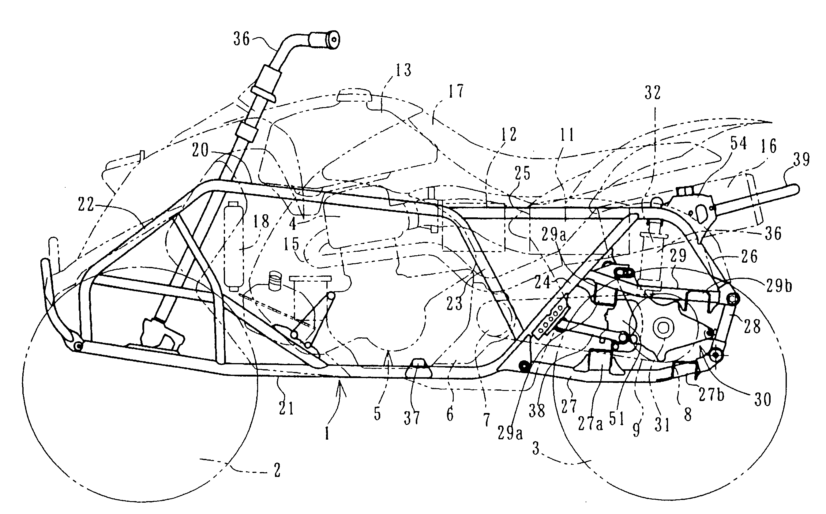
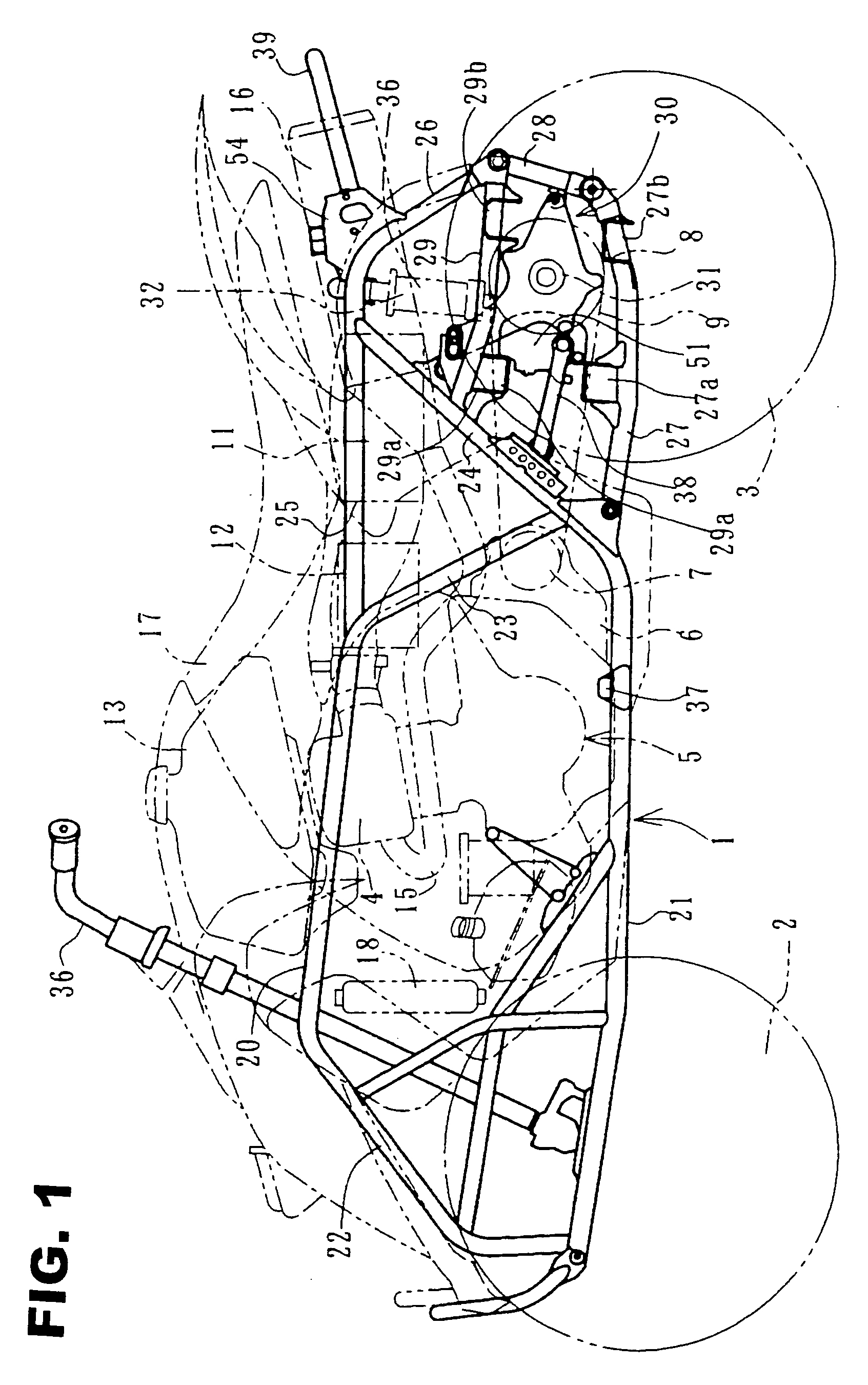
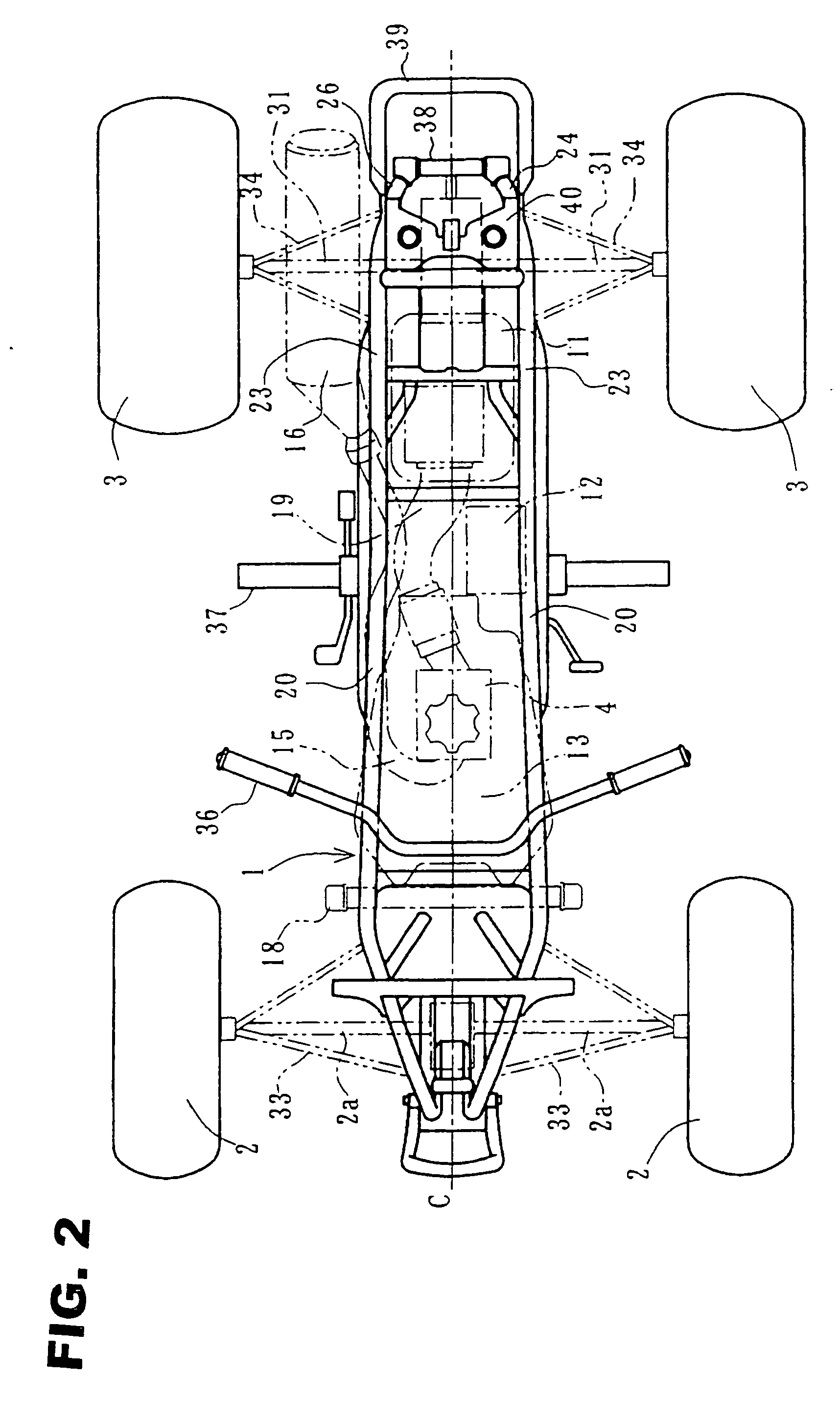
[0022]FIG. 1 is a left-hand side view of an essential portion of a four-wheeled buggy vehicle according to an embodiment. This four-wheeled buggy vehicle is a buggy type irregular terrain running vehicle. The vehicle has a pair of left and right front wheels 2 and rear wheels 3 at the front and the rear, respectively, of a body frame 1. The wheels are low-pressure balloon tires with a relatively large diameter.

[0023] An engine 5 with a forward tilting cylinder 4 is mounted at an almost-middle position of the body frame 1. A crankcase 6 constituting a lower portion of the engine 5 also serves as a transmission case. The crankcase 6 is provided with a driving sprocket 7 at its rear portion. A chain 9 is spanned between the driving sprocket 7 and...


PUM


Abstract

A joint structure for an independent system designed to improve the maintenance performance of a rear wheel suspension. Rear wheel axles extend leftward and rearward from a final case supported by the rear portion of a body frame to independently suspend respective left and right rear wheels. The respective rear wheel axles are coupled to left-hand and right-hand joints on the left and right sides, respectively, of the final case. A driven sprocket engaging with a chain is attached to the left-hand joint and a separate holder is detachably attached to the front of the final case. A joint-part shaft of the right-hand joint is supported by the final case via a bearing and also a brake disk is attached thereto. A male-shaped joint-part shaft integrally extending from the left-hand joint is fitted into the female-shaped joint-part shaft for integrally rotatable coupling.

Description

CROSS-REFERENCE TO RELATED APPLICATION [0001] The present application claims priority under 35 U.S.C. §119 to Japanese Patent Application No. 2005-287712, filed Sep. 30, 2005, the entire contents of which are hereby incorporated by reference. BACKGROUND OF THE INVENTION [0002] 1. Field of the Invention [0003] The present invention relates to a joint structure for an independent suspension and more particularly to a coupling structure advantageous to respective outer races constituting left and right joints. [0004] 2. Description of Background Art [0005] Examples of a coupling structure for respective outer races constituting left-hand and right-hand joints in an independent suspension include the following structure: A joint-part shaft is provided for each of the outer races and fitted from the left and right to a tubular member formed with spline grooves on the internal surface thereof. Thus, the tubular member is spline coupled to the left-hand and right-hand joint-part shafts for...

Claims


Application Information

Patent Timeline
Patent Type & Authority Applications(United States)
IPC IPC(8): B60G21/05B60G3/12B60B35/14B60B35/16B62K5/00B62K5/01
CPCB60G3/20B60G2200/144B60G2300/12B60G2300/13
Inventor SEKI, BUNZO
Owner HONDA MOTOR CO LTD
Why Eureka
Try Eureka