Micro relay

a micro-relay and relay technology, applied in the direction of snap-action arrangements, instruments, soldering devices, etc., can solve the problem of large thickness of the relay, and achieve the effect of easing the pressure which acts on the pressure spring pi

Inactive Publication Date: 2006-11-09
MATSUSHITA ELECTRIC WORKS LTD
View PDF3 Cites 3 Cited by
  • Summary
  • Abstract
  • Description
  • Claims
  • Application Information

AI Technical Summary

Benefits of technology

[0023] Preferably, the pressure spring piece has a meandering part which meanders. By providing the meandering part, the length of the pressure spring piece is lengthened, so that the pressure which acts on the pressure spring piece is eased.
[0024] Preferably, the movable plate is made of a semiconductor substrate and has a hole extending from an upper surface to a undersurface, and the magnetic material is disposed on a surface of the movable plate so that it closes one end of the hole, and the armature block further has a second magnetic material or a metal piece, and the second magnetic material or the metal piece is disposed so that it closes an other end of the hole, and the magnetic material and the second magnetic material or the metal piece are jointed to each other inside the hole by laser welding, and the movable plate is sandwiched between the magnetic material and the second magnetic material or the metal piece. In this case, warpage and so on of the movable plate caused by difference of thermal expansion coefficient between the movable plate and the magnetic material can be suppressed.

Problems solved by technology

Therefore, there is a problem that the thickness of the relay is large.

Method used


Image

  • Micro relay
  • Micro relay
  • Micro relay

Examples


first embodiment

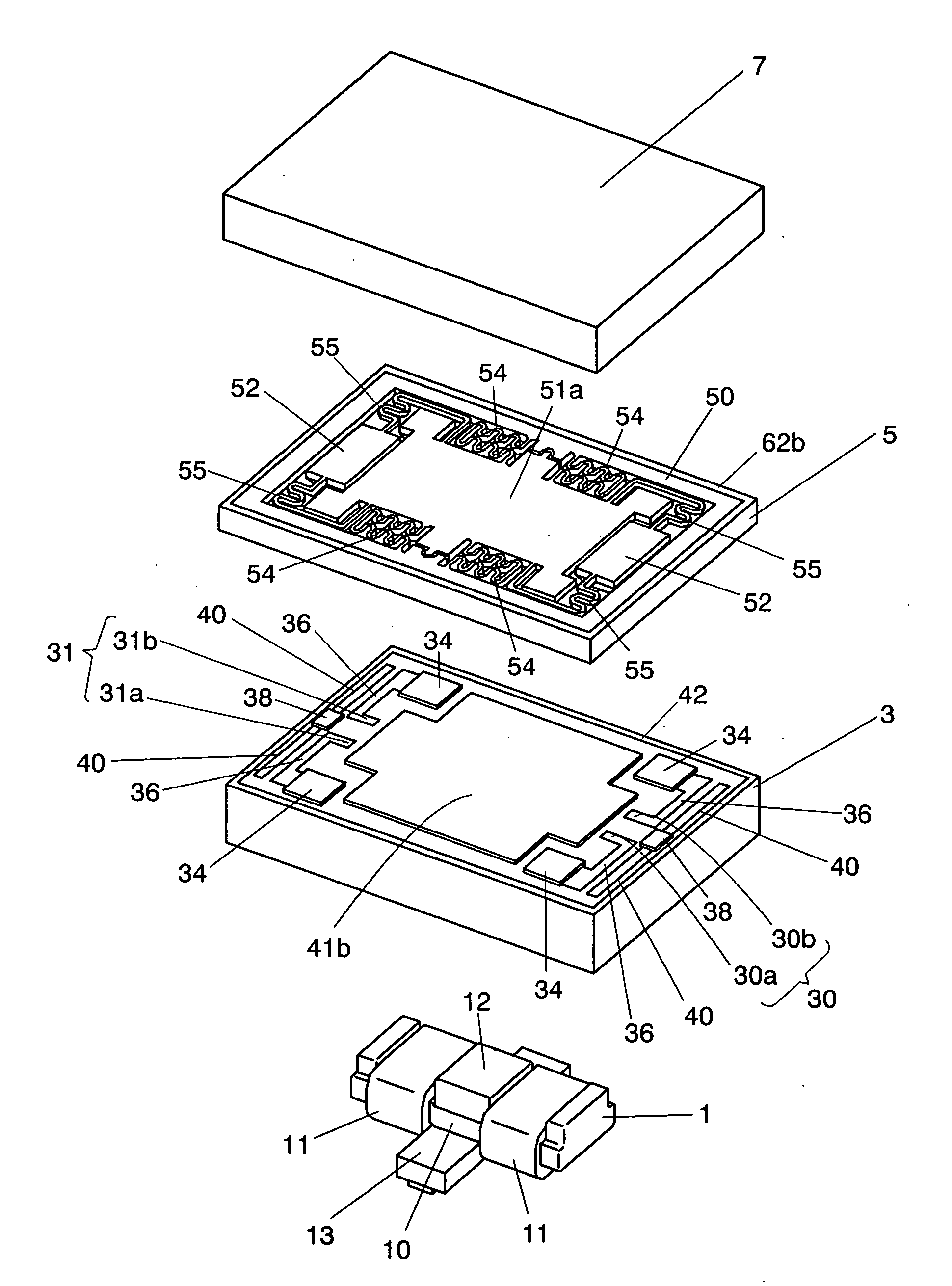
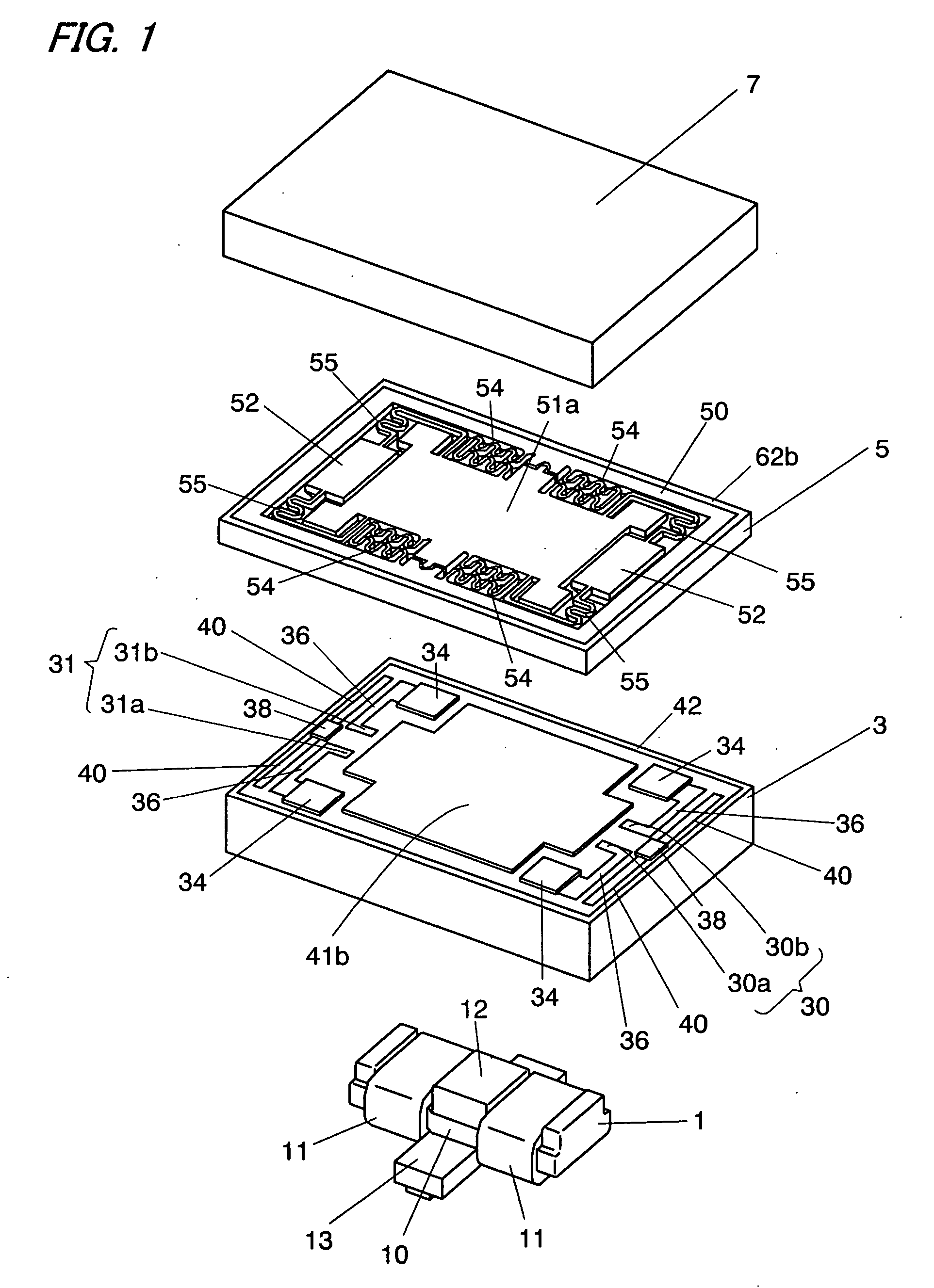
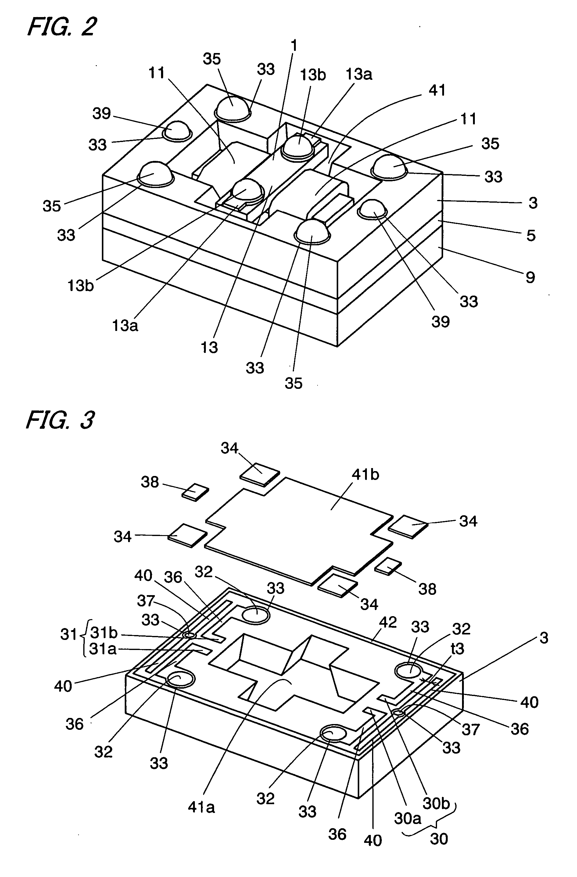
[0057]FIG. 1 shows a micro relay in accordance with a first embodiment of the present invention. The micro relay comprises an electromagnetic device 1, a base substrate 3, an armature block 5, and a cover 7. As shown in FIG. 2, the base substrate 3 has, on the bottom side, a storage recess 41 for accommodating the electromagnetic device 1, and as shown in FIG. 3, the base substrate 3 has two pairs of fixed contacts 30, 31, on an upper surface thereof. The armature block 5 comprises a frame 50 secured to the upper surface of the base substrate, a movable plate 51a disposed inside the frame 50 and supported rotatably by the frame 50 through supporting spring pieces 54, and movable contact bases 52 having movable contacts 53 on an undersurface thereof and supported by the movable plate 51a through pressure spring pieces 55. As shown in FIG. 4, the movable plate 51a cooperates with a magnetic material 51b provided on an undersurface thereof to define an armature 51, and is driven by the...

second embodiment

[0093]FIG. 21 shows a micro relay in accordance with a second embodiment of the present invention. The basic composition of this embodiment is identical to the first embodiment except the base substrate and the armature block, so the similar part of these embodiments are identified by the same reference character and no duplicate explanation is made here.

[0094] In this embodiment, the pair of the fixed contacts 31 of the first embodiment is integrated with the ground trace 40 and is grounded. And, as shown in FIG. 22, two movable contacts 53 are connected to each other through a conductive trace 66 formed on the undersurface of the movable plate 51a. That is, the micro relay of this embodiment is a SPST (Single-Pole Single-Throw) micro relay having one normally open or closed contact. In addition, a shape of the supporting spring piece 54 of the meandering part 54a is different from the shape of the first embodiment, and the pressure spring piece 55 does not have a meandering part....


PUM

PropertyMeasurementUnit
thicknessaaaaaaaaaa
thicknessaaaaaaaaaa
thicknessaaaaaaaaaa

Abstract

The micro relay of the present invention comprises a base substrate 3, an armature block 5, and a cover 7. The base substrate 3 has a storage recess 41 for accommodating an electromagnetic device 1. The storage recess is composed of a hole 41a penetrating the base substrate 3 and a thin storage recess lid fixed on the one surface of the base substrate to close the hole. The electromagnetic device 1 is isolated from a contact mechanism by the storage recess lid 41b to increase the reliability of the contacts. The electromagnetic device 1 includes a yoke 10, a coil 11 wound around the yoke to generate a flux in response to an exciting current, and a permanent magnet 12 secured to the yoke to generate a flux flowing through an armature 51 and the yoke 10. Because the permanent magnet 12 is secured to the yoke 10, this micro relay can reduce the thickness.

Description

TECHNICAL FIELD [0001] The present invention relates to a micro relay manufactured by means of semiconductor micromachining technology. BACKGROUND ART [0002] Japanese Non-examined Patent Publication No. 5-114347 discloses a micro relay manufactured by means of semiconductor micromachining technology. This micro relay is an electromagnetic relay which opens or closes contacts using electromagnetic force of an electromagnetic device, and comprises a base substrate having an electromagnetic device, a frame secured to the base substrate through a spacer, and an armature having a permanent magnet and disposed inside the frame. In comparison with an electrostatic relay which opens or closes contacts using Coulomb's force, such electromagnetic relay can have large driving force, so such electromagnetic relay can enhance the reliability of the relay by increasing contact pressure. [0003] However, in the above micro relay, because the permanent magnet is secured to the armature, it is necess...

Claims


Application Information

Patent Timeline
Patent Type & Authority Applications(United States)
IPC IPC(8): H01H51/22B81B3/00B81B5/00B81C3/00H01H49/00H01H50/00H01H50/02H01H50/04H01H50/14H01H50/18H01H50/36
CPCH01H2050/007H01H50/005H01H50/02H01H50/04H01H50/18H01H50/36
Inventor HASHIMOTO, TAKESHIFURUMOTO, NORITERUOKUMURA, NAOKIENOMOTO, HIDEKISADAMORI, TAKESHIKISHIMOTO, SHINICHISHIMOMURA, TSUTOMUSAKAI, KOUJIHORI, MASAMI
Owner MATSUSHITA ELECTRIC WORKS LTD
Why Eureka
Try Eureka