
Energy recovery device for plasma display panel

Inactive Publication Date: 2006-11-09
KONINKLIJKE PHILIPS ELECTRONICS NV
View PDF11 Cites 7 Cited by
  • Summary
  • Abstract
  • Description
  • Claims
  • Application Information

AI Technical Summary

Benefits of technology

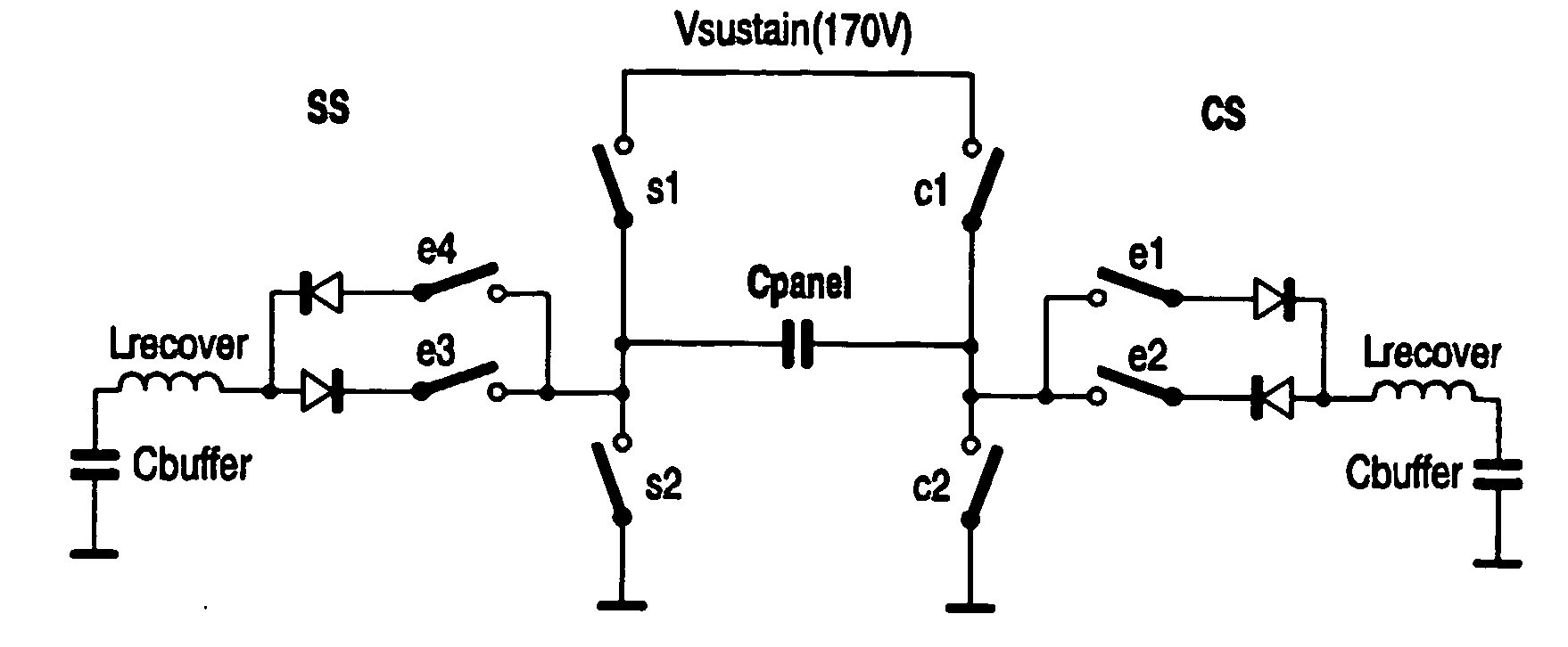
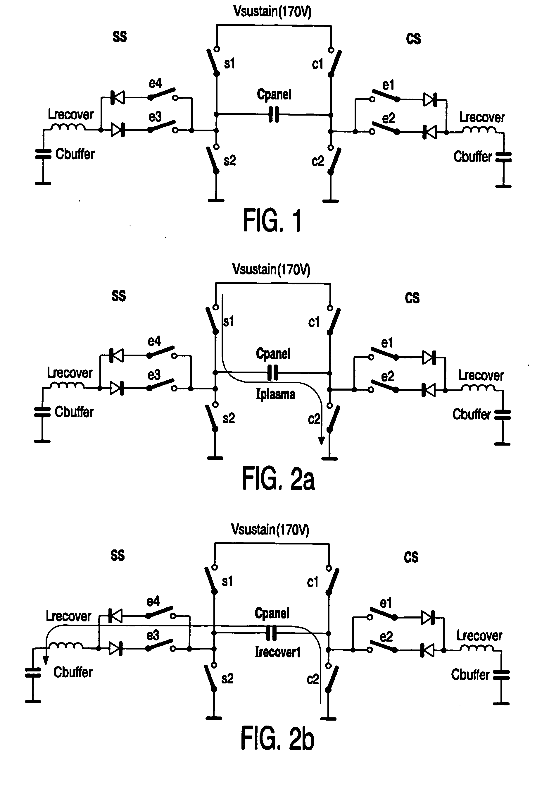
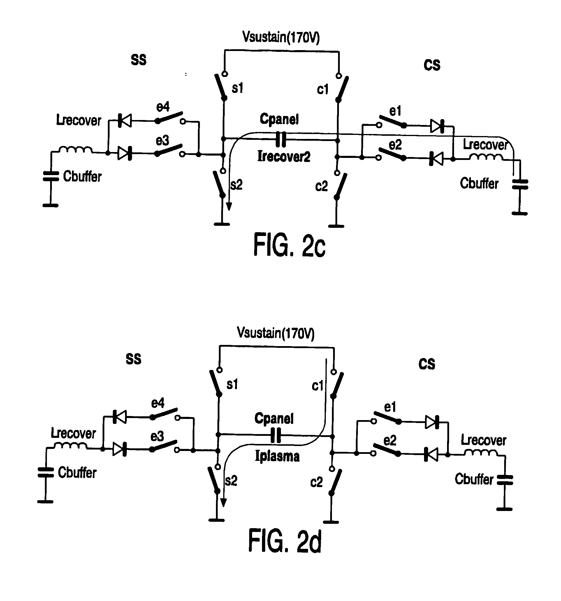
[0027] According to the teachings of the present invention, energy recovering storing means are pre-charged before the corresponding energy recovery period wherein the energy recovery storing means is discharged again. By pre-charging of the energy recovery storing means the requirement for the provision of an additional voltage step can be obviated, and, in turn, an improved EMI figure can be reached. In particular, a full voltage swing in recovering the stored energy in the panel capacitance can be achieved.
[0028] A further advantage of the topology of the present invention is that fewer switches than in the prior art are required for performing an energy recovery sustain cycle. Consequently, a lower number of switches results in a cheaper constructions of the whole device.
[0035] Inverting the panel voltage with a full voltage swing is advantageous for the first and second switches in particular in case such switches consists of MOSFETs. Namely, when such a switch is activated (closed) its drain-source voltage is zero. With no voltage present over such a switch when activated, its losses are greatly reduced. This in turn is beneficial for power dissipation, EMI and energy recovery efficiency.
[0036] In a still further preferred embodiment, the second voltage source comprises a higher potential terminal and a lower potential terminal, the higher potential terminal being connected to the second switch and the lower potential terminal being connected to the first node. So, the first and second voltage sources are coupled in a cascade. This leads to the advantage that the second voltage source does not need to generate the full voltage level relative to ground, but only the difference between the first voltage level and the second voltage level resulting in a simpler construction.

Problems solved by technology

So, the oscillations are damped which, however, dissipates energy.
Further, some voltage steps still occur at least during hard switching.
However, it is difficult to decouple the voltage of the half bridges close to the panel.
However, as far as EMI is concerned, this concept is less EMI friendly.
However in the prior art topologies certain losses arise.
However, such an additional voltage step with a very steep slope is not considered to be very beneficial for EMI.

Method used


Image

  • Energy recovery device for plasma display panel
  • Energy recovery device for plasma display panel
  • Energy recovery device for plasma display panel

Examples


Embodiment Construction

[0049]FIG. 5 schematically shows a basic circuit diagram of a topology according to a first preferred embodiment. Instead of a full-bridge driver construction, a half driver construction is implemented in the energy recovery sustain topology shown in FIG. 5. As a consequence of this, the supply voltage for the driver has to be doubled. In the embodiment of FIG. 5, two 170V sustain voltage supplies are stacked, by which the common side of the panel is connected in the middle of the two supplies. Accordingly, the switches used have to withstand twice the sustain voltage, thus 340V.

[0050] A resonant path is formed by an inductor Lrecover connected in parallel with the display panel. In this topology, the inductor Lrecover is placed in parallel with the panel capacitance Cpanel without the use of any extra switches. As shown in FIG. 5, at the common side the first terminals of the display panel (depicted as its capacitance Cpanel only) and of the energy recovery inductor Lrecover are c...


PUM


Abstract

Disclosed is an energy recovery device for recovering energy in a display panel, in particular a plasma display panel, wherein an energy recovery storing unit (Lrecover) is coupled with the display panel during an energy recovery period following a sustain period. The particularity of the invention is that the energy recovery recover storing unit (Lrecover) is charged in said sustain step.

Description

FIELD OF THE INVENTION [0001] The present invention relates to an energy recovering sustain device for a display panel, in particular a plasma display panel (PDP), comprising an energy recovery storing means adapted for coupling with the display panel for performing an energy recovery period following a sustain period. [0002] Further, the present invention relates to a driving apparatus for driving a display panel, in particular a plasma display panel (PDP), comprising the mentioned energy recovery sustain device. Still further, the present invention relates a display apparatus for displaying an image, comprising a display panel, in particular plasma display panel (PDP), and such an energy recovery sustain device. BACKGROUND OF THE INVENTION [0003] In recent years, a thin display apparatus has been requested in conjunction with an increase in size of the display panel. The plasma display panel (hereinafter simply referred to as “PDP”) is expected to become one of the most important ...

Claims


Application Information

Patent Timeline
IPC IPC(8): G09G3/28G09G3/296
CPCG09G2330/06G09G3/2965G09G3/296
Inventor VOSSEN, FRANSISCUS JACOBUSDERKSEN, SANDER
Owner KONINKLIJKE PHILIPS ELECTRONICS NV
Learn More