
Rake receiver with time-shared fingers

a rake receiver and finger technology, applied in the field of wireless receivers, can solve the problems of large hardware area, random noise of sequences in receivers, and large hardware area of typical rake receivers

Inactive Publication Date: 2006-11-09
AVAGO TECH INT SALES PTE LTD
View PDF36 Cites 6 Cited by
  • Summary
  • Abstract
  • Description
  • Claims
  • Application Information

AI Technical Summary

Benefits of technology

[0018] Problems in the prior art are addressed in accordance with the principles of the present invention by replacing multiple physical finger instances with simplified fingers that are time-multiplexed to process each of the path components during a different processing cycle, so that the multiple fingers can share the same demodulating hardware engine. A processing cycle is a chip period, defined by the chip rate. Different chip periods are assigned to different fingers, so that each finger processes its own received data using the shared demodulating hardware. In the chip period assigned to a particular finger/path, multiple received bits (equal to the number of fingers sharing the same hardware) for that finger are demodulated to “catch up” with those “missing” chip periods that were assigned to demodulate other fingers/paths. An input sample buffer is used to store received chip data for a given finger before the data is demodulated.
[0019] In one embodiment, the present invention provides a rake receiver for processing a multi-path input signal received from a communications channel. Each multi-path component of the multi-path input signal comprises one or more symbols. The rake receiver comprises a plurality of fingers and a demodulator. Each of the plurality of fingers is adapted to receive the multi-path input signal and provide a sequence of input samples corresponding to a multi-path component of the multi-path input signal. The demodulator is adapted (i) during a single clock period, to receive and process one or more input samples corresponding to only one of the fingers, (ii) for each of the fingers, to accumulate multiple processed input samples to form a symbol, and (iii) to provide the formed sym

Problems solved by technology

While, in some applications, these multiple components may result in interference, e.g., ghosting on the display of an analog television receiver, Code Division Multiple Access (CDMA) systems intentionally make use of these multiple components.
Scrambling is typically performed using a pseudorandom noise (PN) code sequence, which results in a sequence appearing as random noise to a receiver that does not have the identical code sequence.
As can be seen in the exemplary rake receiver 100 of FIG. 1, due to the number of operations that it performs and the multiple instances of each operation necessitated by the plurality of fingers, the hardware of a typical rake receiver is relatively complex.
Moreover, a typical rake receiver requires a large amount of hardware area and dissipates a relatively large amount of power because of its multiple fingers.
Accordingly, the bandwidth usage may be uneven.
Moreover, this implementation still typically involves the dissipation of substantial power due to the high-frequency clock rate.

Method used


Image

  • Rake receiver with time-shared fingers
  • Rake receiver with time-shared fingers
  • Rake receiver with time-shared fingers

Examples


Embodiment Construction

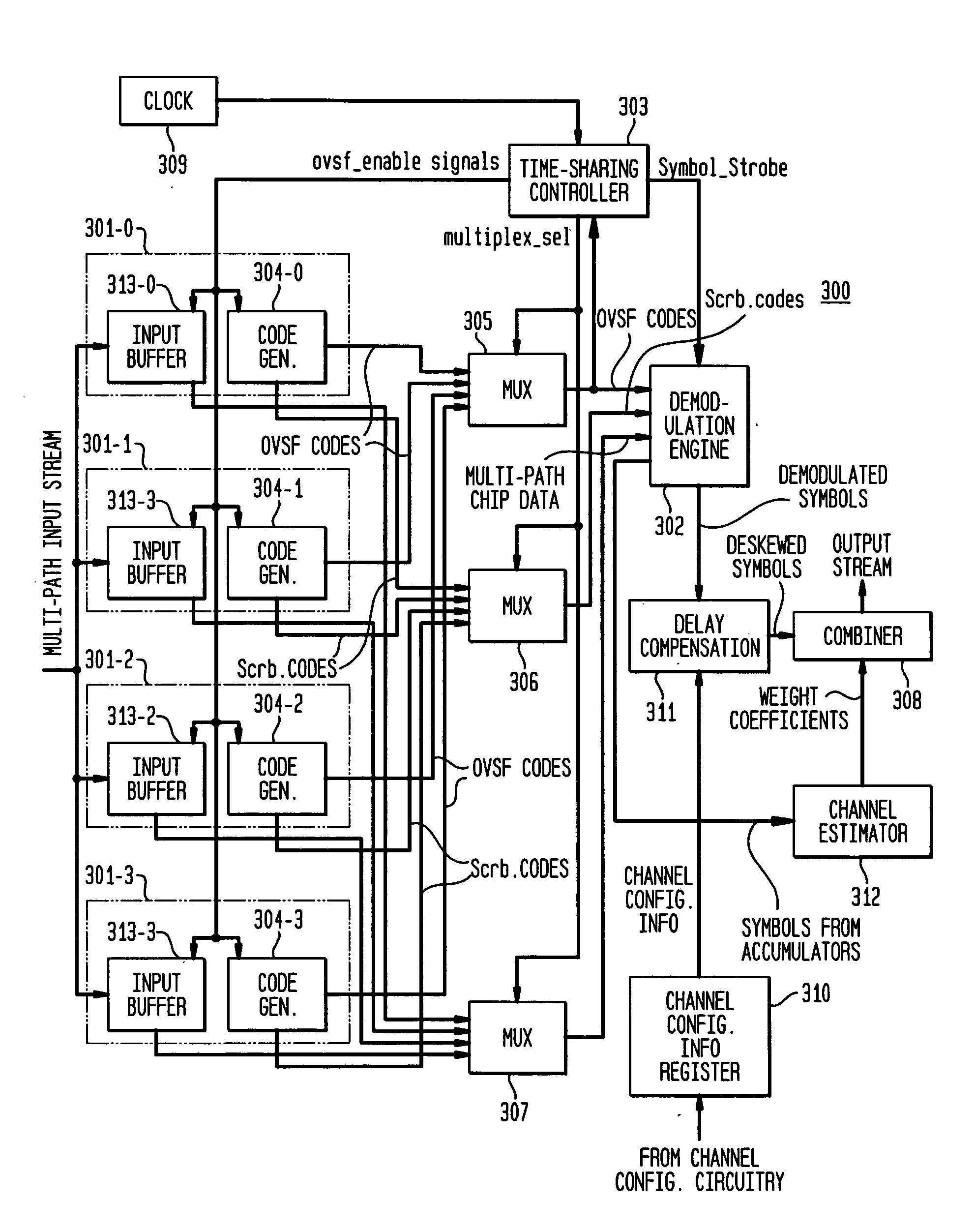
[0031]FIG. 3 is a block diagram illustrating the structure of an exemplary rake receiver 300 consistent with one embodiment of the present invention. As shown, rake receiver 300 has four fingers 301-0 to 301-3, each of which collects energy for a particular multi-path component of the received signal. Unlike the prior art, it should be noted that fingers 301-0 to 301-3 do not include any hardware for demodulation, descrambling, despreading, or filtering, since these operations are instead (preferably although not necessarily) performed at a single demodulation engine 302, which is shared by all four fingers 301-0 to 301-3. If despreading is to be performed at the demodulation engine 302, then an input sample will contain multiple chips. During each chip period, all four fingers are active and simultaneously process a single data sample from the multi-path signal. However, the outputs of the fingers are multiplexed so as to provide chip data from only one finger at a time to demodula...


PUM


Abstract

A rake receiver for processing a multi-path input signal received from a communications channel, wherein each multi-path component of the multi-path input signal comprises one or more symbols, comprises a plurality of fingers and a demodulator. Each of the plurality of fingers is adapted to receive the multi-path input signal and provide a sequence of input samples corresponding to a multi-path component of the multi-path input signal. The demodulator is adapted (i) during a single clock period, to receive and process one or more input samples corresponding to only one of the fingers, (ii) for each of the fingers, to accumulate multiple processed input samples to form a symbol, and (iii) to provide the formed symbols for all fingers.

Description

BACKGROUND OF THE INVENTION [0001]1. Field of the Invention [0002] The present invention relates to wireless receivers, and, in particular, to rake receivers for processing a signal that has been subjected to a multi-path channel. [0003]2. Description of the Related Art [0004] When a signal travels through a real-world environment, it often reaches a receiver by multiple paths. These paths occur as a result of the signal reflecting, diffracting, and scattering from various elements in the environment, e.g., mountains, trees, and buildings. Multi-path components are essentially time-delayed variants of a single signal. While, in some applications, these multiple components may result in interference, e.g., ghosting on the display of an analog television receiver, Code Division Multiple Access (CDMA) systems intentionally make use of these multiple components. [0005] The basic principle of CDMA systems is orthogonal coding, whereby, instead of assigning specific frequencies or time sl...

Claims


Application Information

Patent Timeline
IPC IPC(8): H04B1/00
CPCH04B1/7117
Inventor ZHOU, GONGYU
Owner AVAGO TECH INT SALES PTE LTD
Features
  • Generate Ideas
  • Intellectual Property
  • Life Sciences
  • Materials
  • Tech Scout
  • Unparalleled Data Quality
  • Higher Quality Content
  • 60% Fewer Hallucinations
Learn More