Multi-mode internal imaging

a multi-mode, imaging technology, applied in the field of multi-modal imaging, can solve the problems of increasing the cost of each of these traditional imaging systems, increasing the cost of mri and computer tomography (ct) systems, and increasing the cost of ct systems

Inactive Publication Date: 2006-11-09
XENOGEN CORP
View PDF51 Cites 12 Cited by
  • Summary
  • Abstract
  • Description
  • Claims
  • Application Information

AI Technical Summary

Problems solved by technology

However, the cost of each of these traditional imaging systems has become a barrier to such combination; and becomes even more prohibitive when contemplating multiple techniques at a single site.
For instance, an MRI and computer tomography (CT) system can cost millions of dollars.
In addition, most traditional imaging systems have practical complications that inhibit implementation in a multiple imaging system environment.
Positron emission tomography (PET) centers are geographically limited to be close to a particle accelerator device that produces the short-lived radioisotopes used in the technique.
Also, transferring an object to be imaged between different imaging systems would be difficult, such as it would be difficult to maintain the spatial accuracy provided by each system without compromise due to object transfer between the systems.

Method used


Image

  • Multi-mode internal imaging
  • Multi-mode internal imaging
  • Multi-mode internal imaging

Examples


Embodiment Construction

[0033] In the following detailed description of the present invention, numerous specific embodiments are set forth in order to provide a thorough understanding of the invention. However, as will be apparent to those skilled in the art, the present invention may be practiced without these specific details or by using alternate elements or processes. In other instances well known processes, components, and designs have not been described in detail so as not to unnecessarily obscure aspects of the present invention.

1. Overview

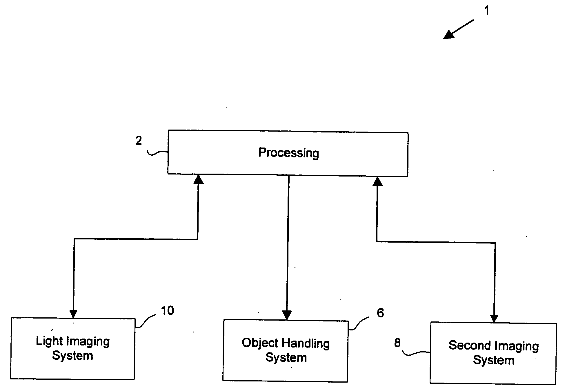
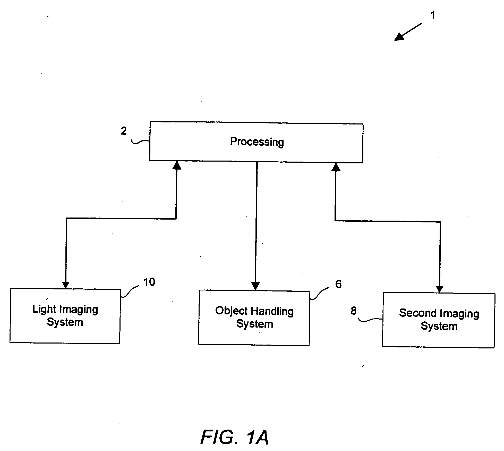
[0034]FIG. 1A illustrates a simplified system 1 for providing multiple modes of imaging data for an internal portion of an object in accordance with one embodiment of the present invention. System 1 comprises a light imaging system 10, a second imaging system 8, an object handling system 6, and at least one processor 2. The object handling system 6 transfers an object (or sample) being imaged between an interior cavity of the light imaging system and a receivin...


PUM

PropertyMeasurementUnit
wavelength rangeaaaaaaaaaa
speedaaaaaaaaaa
speedaaaaaaaaaa

Abstract

The invention described herein provides systems and methods for multi-modal imaging with light and a second form of imaging. Light imaging involves the capture of low intensity light from a light-emitting object. A camera obtains a two-dimensional spatial distribution of the light emitted from the surface of the subject. Software operated by a computer in communication with the camera may then convert two-dimensional spatial distribution data from one or more images into a three-dimensional spatial representation. The second imaging mode may include any imaging technique that compliments light imaging. Examples include magnetic resonance imaging (MRI) and computer topography (CT). An object handling system moves the object to be imaged between the light imaging system and the second imaging system, and is configured to interface with each system.

Description

CROSS-REFERENCE TO RELATED APPLICATION [0001] This application claims priority under U.S.C. §120 from co-pending U.S. patent application Ser. No. 10 / 881,707, filed Jun. 29, 2004 and entitled, “MULTI-MODE INTERNAL IMAGING”, which claimed priority under 35 U.S.C. §119(e) from co-pending U.S. Provisional Patent Application No. 60 / 484,186 entitled “Multi-Mode Internal Imaging”; both of these patent applications are incorporated by reference for all purposes.FIELD OF THE INVENTION [0002] The present invention relates to systems and methods for obtaining multiple representations of an internal portion of an object, which is particularly useful in research and imaging applications. In particular, the present invention relates to multi-modal imaging with light and another type of imaging. BACKGROUND OF THE INVENTION [0003] Today researchers and imaging practitioners use any one of a number of non-invasive imaging techniques to produce an internal image. These techniques employ X-rays, magne...

Claims


Application Information

Patent Timeline
Patent Type & Authority Applications(United States)
IPC IPC(8): A61B5/05A61B5/00A61B5/055A61B6/03A61B8/13C07DE04F21/00G01N21/64G01N21/76G01N35/00G01T1/164G01T1/29
CPCA61B5/0059A61B5/0077A61B6/032A61B6/5247A61B8/13A61B8/4416A61B6/037G01N21/76G01N35/0099G01T1/1603G01T1/1648G01T1/2985A61B6/4417G01N21/6456A61B5/0035A61B2503/40
Inventor CABLE, MICHAEL D.RICE, BRADLEY W.NILSON, DAVID
Owner XENOGEN CORP
Why Eureka
Try Eureka