Endovascular stapler

a technology of endovascular and stapler, which is applied in the direction of surgical staples, surgical forceps, blood vessels, etc., can solve the problems of type 1 endoleak with aneurysm sac reperfusion, enlargement and rupture, and insufficient coverage of renal artery orifices,

Inactive Publication Date: 2006-11-09
EDRICH HEALTH TECH
View PDF33 Cites 87 Cited by
  • Summary
  • Abstract
  • Description
  • Claims
  • Application Information

AI Technical Summary

Benefits of technology

[0025] The spring may permit the outer section to ratchet about the inner section of the trigger when the trigger is moved away from the handle, such that the pusher remains in the advanced position.
[0047] A still further embodiment of the present invention discloses a method of repairing an endograft in a vessel with an endovascular stapler having a distal end and a biasing mechanism associated therewith, the method comprising inserting the distal end of the endovascular stapler into the endograft, advancing the biasing mechanism so as to push the distal end of the endovascular stapler against the endograft without completely inhibiting blood flow, discharging a staple from the endovascular stapler into the endograft such that the staple forms a pair of curved legs connected by a central portion.
[0048] The method may also include the steps of partially retracting the biasing mechanism to permit rotation of the distal end of the endovascular stapler, rotating the distal end of the endovascular staple, advancing the biasing mechanism so as to push the distal end of the endovascular stapler against the endograft without completely inhibiting blood flow, discharging a staple from the endovascular stapler into the endograft such that the staple forms a pair of curved legs connected by a central portion.
[0076] The step of discharging may serve to advance a staple pusher within the stapler for discharging the first staple. The first staple may advance along a staple guide, the staple guide retarding the return of the first staple to its natural condition. The staple pusher may include a pivoting portion and the step of discharging may rotate the pivoting portion into the central portion of the first staple such that the central portion of the first staple abuts the endograft.
[0099] The vessel may flow blood from a heart and the step of deploying may drive the first staple away from the heart in the direction of blood flow.

Problems solved by technology

Notwithstanding the various materials utilized, migration of the grafts over time remains a problem.
Caudad device migration is known to lead to a Type 1 endoleak with aneurysm sac reperfusion, enlargement and rupture.
Cephalad device migration may lead to coverage of the renal artery orifices and renal insufficiency.
One known factor is poor patient selection.
Patients with cone shaped aortic necks, severe neck tortuosity, short necks or who have a laminated thrombus present at the landing site are generally susceptible to device migration problems.
Other device migration issues are caused by changing aortic morphology following device implantation.
Finally, migration may be caused by device structural fatigue and device design related issues.
These late conversions are, unfortunately, associated with a high mortality rate.
Treatment options for the cephalad migrations are even less attractive.
In the face of continued migration, resignation may be the only option as such migration may lead to renal insufficiency requiring hemodialysis.
To permit device removal, a typical conversion in this case involves supra-celiac aortic cross-clamping, and its associated problems.
Prior attempts at fixation of migrating devices, including additions of hooks, barbs, tackers, and other fastening devices have proven to be insufficient or impractical.

Method used


Image

  • Endovascular stapler
  • Endovascular stapler
  • Endovascular stapler

Examples


second embodiment

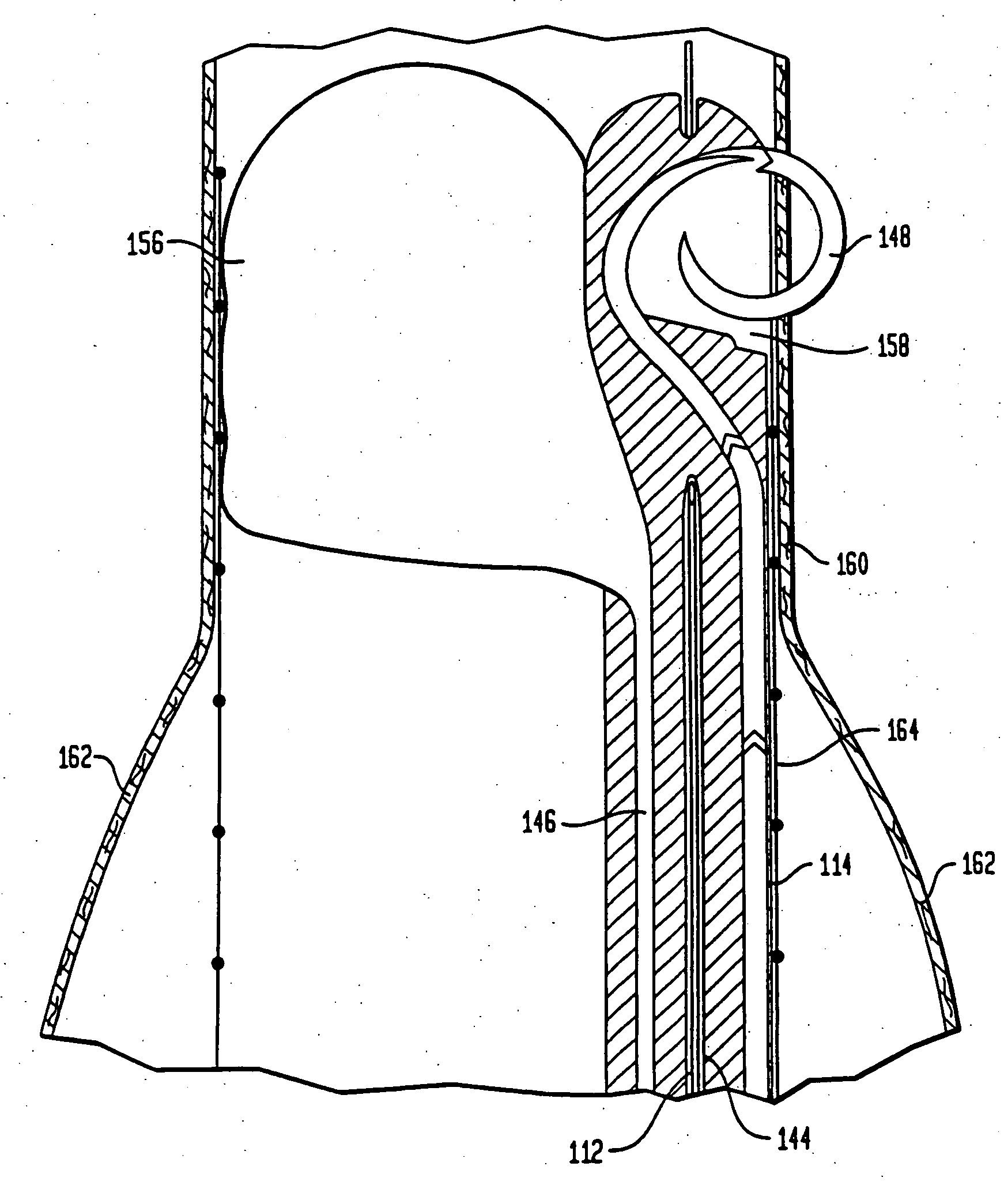
[0197]FIG. 14 depicts a cross-sectional view of a portion of the staple housing 214 of an endovascular stapler (not shown) in accordance with the present invention. In this embodiment, a single staple 248, formed in the shape of an elongated W may be applied to secure a graft 264 against a vessel, shown in FIG. 14 as an aortic wall 260. Typically, the chief function of a stapler in accordance with this embodiment is for use to arrest device migration of a previously placed endograft. Other embodiments employing multiple elongated W-shaped staples may also be used to arrest device migration of a previously implanted endograft or to affix a new endograft. Still further embodiments permit the withdrawal of portions of the stapler which may then be replaced with other portions pre-loaded with a staple for a subsequent firing.

[0198]FIG. 13 depicts a partially cut-away perspective view of a stapler housing 214 and a noncompliant balloon 256 inserted within an aortic wall 260 in preparatio...

first embodiment

[0202] As with the first embodiment, a guide wire channel 244 is also located within the staple housing 214. The guide wire channel 244 permits the use of a guide wire 212 in an “over the wire” system, to properly place the staple exit area 258.

[0203]FIG. 14 also depicts a portion of a noncompliant balloon 256. The noncompliant balloon 256 of the second embodiment may be completely exterior of the staple housing 214. The noncompliant balloon 256 is intended to be inflated such that the staple housing 214 will be pushed against the stent graft 264 such that the stent graft may be firmly apposed against the aortic wall 260.

[0204] Also included within the staple housing 214 is an elongated W-shaped staple 248. As shown in FIG. 15, the staple 248 includes two U-shaped sections 316 connected by a bridge 318. Each of the U-shaped sections 316 of the staple 248 sits against the front surface 320 of the actuator 306. At the extreme ends of the staple 248, the front surface 320 extends out ...


PUM


Abstract

An endovascular stapler for securing an endograft to a vessel is disclosed. The stapler includes a staple housing adapted for storing at least one staple therein, the staple housing having an exit area for discharge of the at least one staple therethrough, an actuating assembly adapted for discharging the at least one staple through the exit area, and a displacement mechanism in operative association with the staple housing near the exit area. The displacement member is operative for pushing the exit area against the endograft when discharging the at least one staple therethrough. The discharged staple forms a plurality of opposed loops connected by a central element upon discharge. Also disclosed are staples and displacement mechanisms adapted for use with surgical instruments such as the present endovascular staplers. The staples may be formed from memory metal or other metal. The displacement mechanisms disclosed include balloons and rigid offsetting devices.

Description

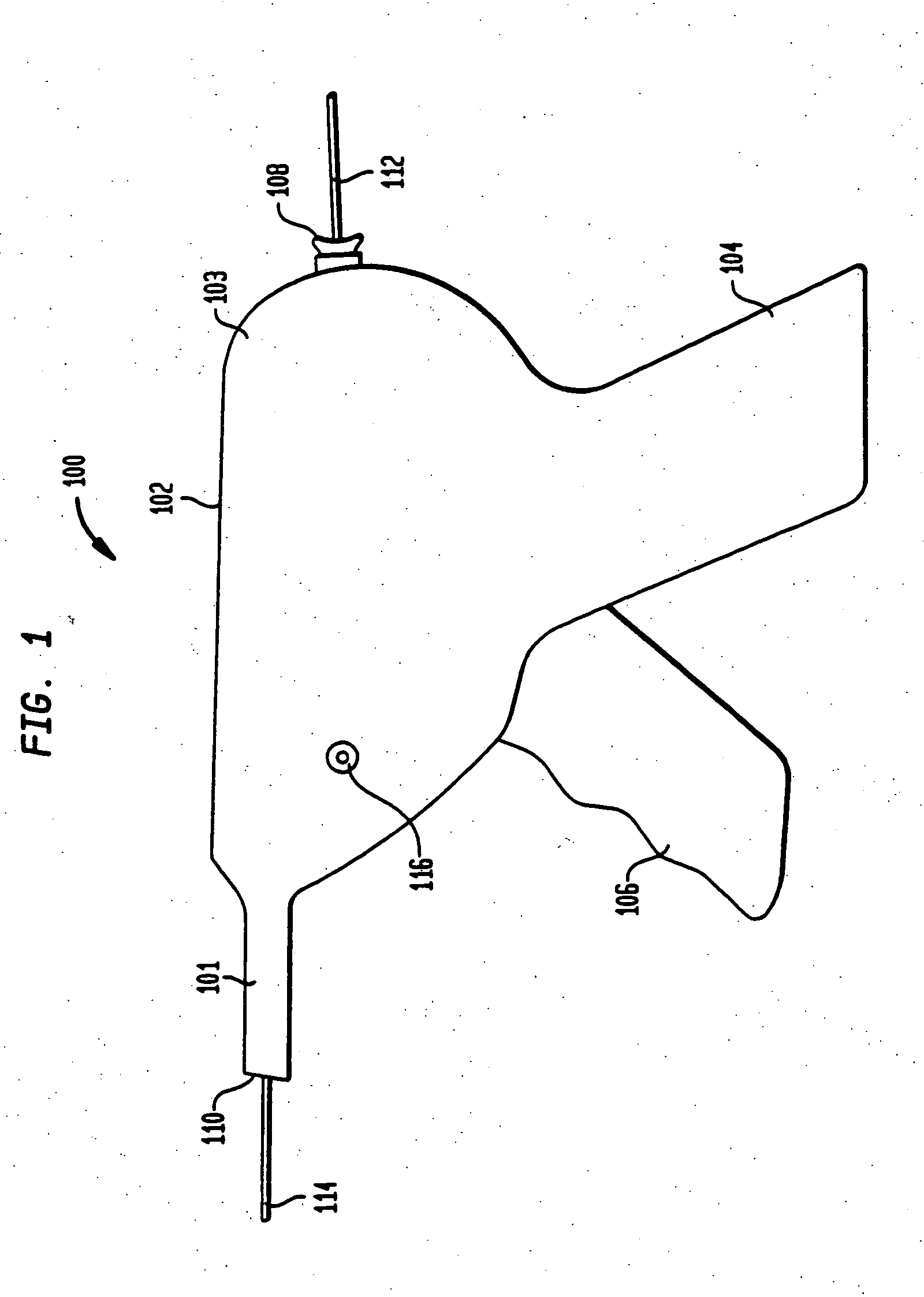
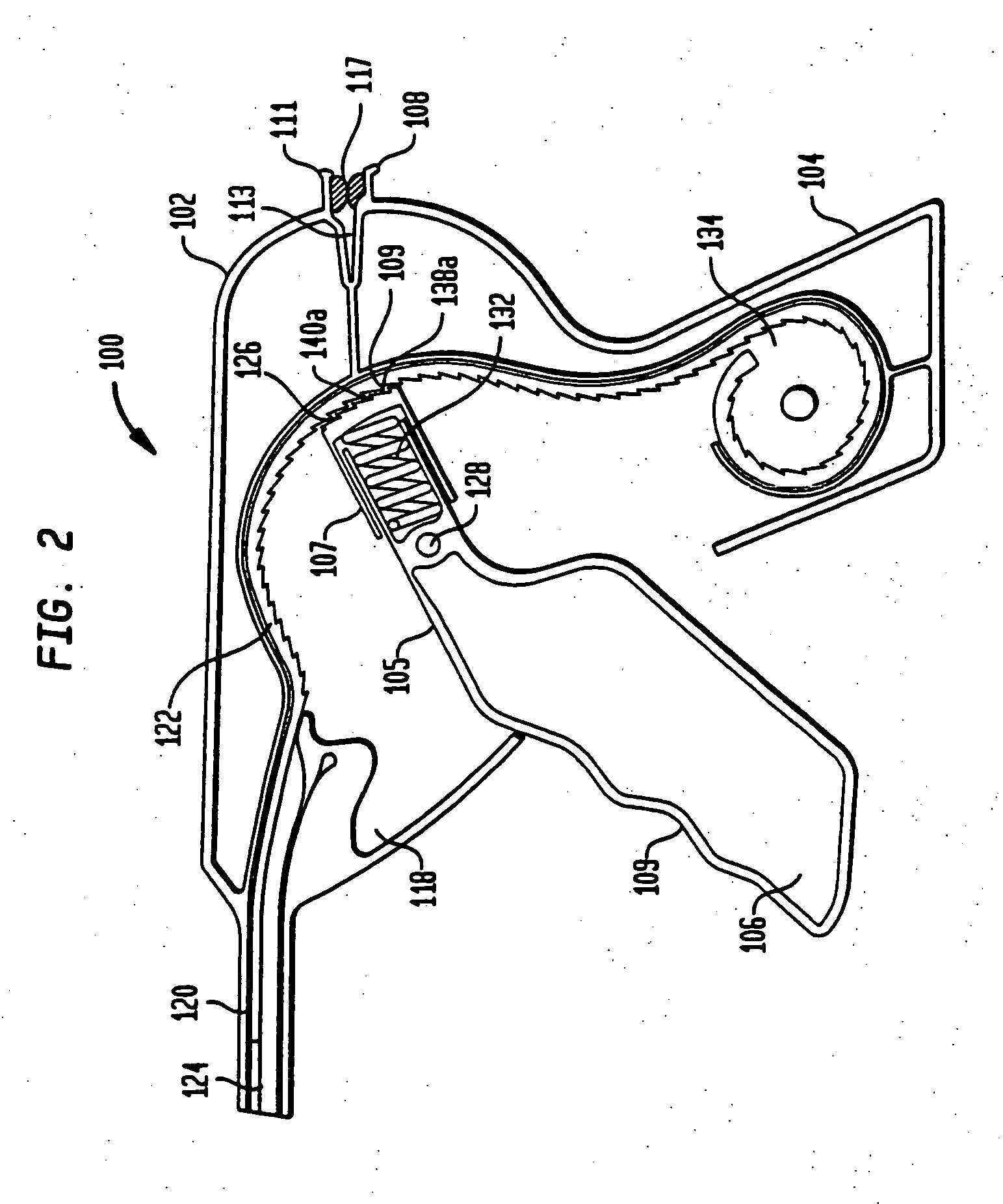
CROSS REFERENCE TO RELATED APPLICATIONS [0001] The present Utility patent application is a divisional application of U.S. Utility patent application Ser. No. 10 / 837,827, filed May 3, 2004, which is a continuation-in-part of U.S. Utility patent application Ser. No. 10 / 737,466 filed Dec. 16, 2003, which claims the benefit of U.S. Provisional Patent Application Ser. No. 60 / 433,692 filed Dec. 16, 2002, and U.S. Provisional Application No. 60 / 501,060 filed Sep. 8, 2003, the disclosures of the foregoing applications are hereby incorporated herein by reference.BACKGROUND OF THE INVENTION [0002] The present invention relates to a stapling device for use in the fixation of endovascular grafts to the walls of vessels. Fixation of grafts utilizing the present invention may be conducted during initial implantation. In addition, the present invention may also be utilized to arrest the vexing complication of proximal or distal migrations following the prior implantation of such grafts. Fixation m...

Claims


Application Information

Patent Timeline
Patent Type & Authority Applications(United States)
IPC IPC(8): A61B17/08A61B17/00A61B17/064A61B17/068A61B17/10A61B17/115A61B17/22A61B17/28A61B19/00
CPCA61B17/10A61B17/0684A61B19/54A61B2017/00557A61B2017/00867A61B2017/0649A61B2017/1157A61B2017/22051A61B2017/22052A61B2017/22069A61B2017/2905A61B2017/2933A61B2019/5425A61F2/07A61B17/0644A61B17/068A61B17/115A61B90/39A61B2090/3925
Inventor EDOGA, JOHN K.RICHARD, THIERRYBACHMAN, ALAN
Owner EDRICH HEALTH TECH
Why Eureka
Try Eureka