Phase adjust using relative error

a relative error and phase adjustment technology, applied in the field of data communication, can solve the problems of significant degrading increasing the level of data distortion, and affecting the performance of the receiver,

Inactive Publication Date: 2006-11-09
AVAGO TECH INT SALES PTE LTD
View PDF5 Cites 23 Cited by
  • Summary
  • Abstract
  • Description
  • Claims
  • Application Information

AI Technical Summary

Benefits of technology

[0007] A system and / or method of adjusting the phase of signals for a system, substantially as shown in and / or described in connection with at least one of the figures, as set forth more completely in the claims.

Problems solved by technology

In operation, however, bandwidth limitations inherent in the data communication media may tend to create increasing levels of data distortion as the data rate increases and as the channel length increases.
In many applications, particularly high speed applications, relatively high levels of ISI may significantly degrade the performance of the receiver.
Inaccuracy in this phase relationships may result in performance degradation of the receiver since the received signal may be equalized at a non-optimum point in time.

Method used


Image

  • Phase adjust using relative error
  • Phase adjust using relative error
  • Phase adjust using relative error

Examples


Embodiment Construction

[0017] The invention is described below, with reference to detailed illustrative embodiments. It will be apparent that the invention may be embodied in a wide variety of forms, some of which may be quite different from those of the disclosed embodiments. Consequently, the specific structural and functional details disclosed herein are merely representative and do not limit the scope of the invention. For example, references to specific structures and processes in the disclosed embodiments should be understood to be but one example of structures and processes that may be used in these or other embodiments in accordance with the teachings provided herein. Accordingly, otherwise restrictive nomenclatures such as “is,”“are,” etc. should be understood to include less restrictive meanings such as “may be,” etc. For convenience, an embodiment of a system constructed or a method practiced according to the invention may be referred to herein simply as an “embodiment.”

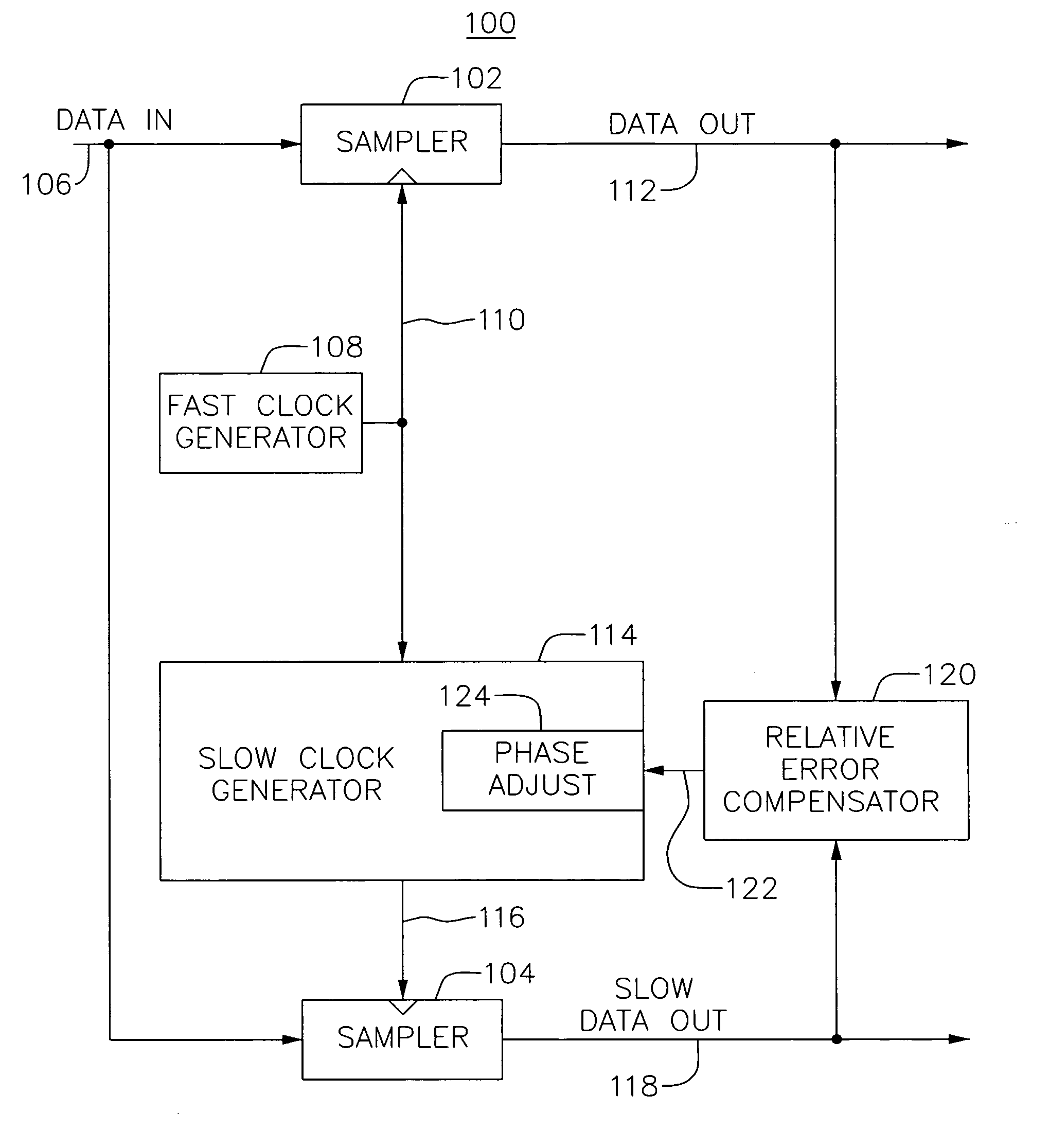
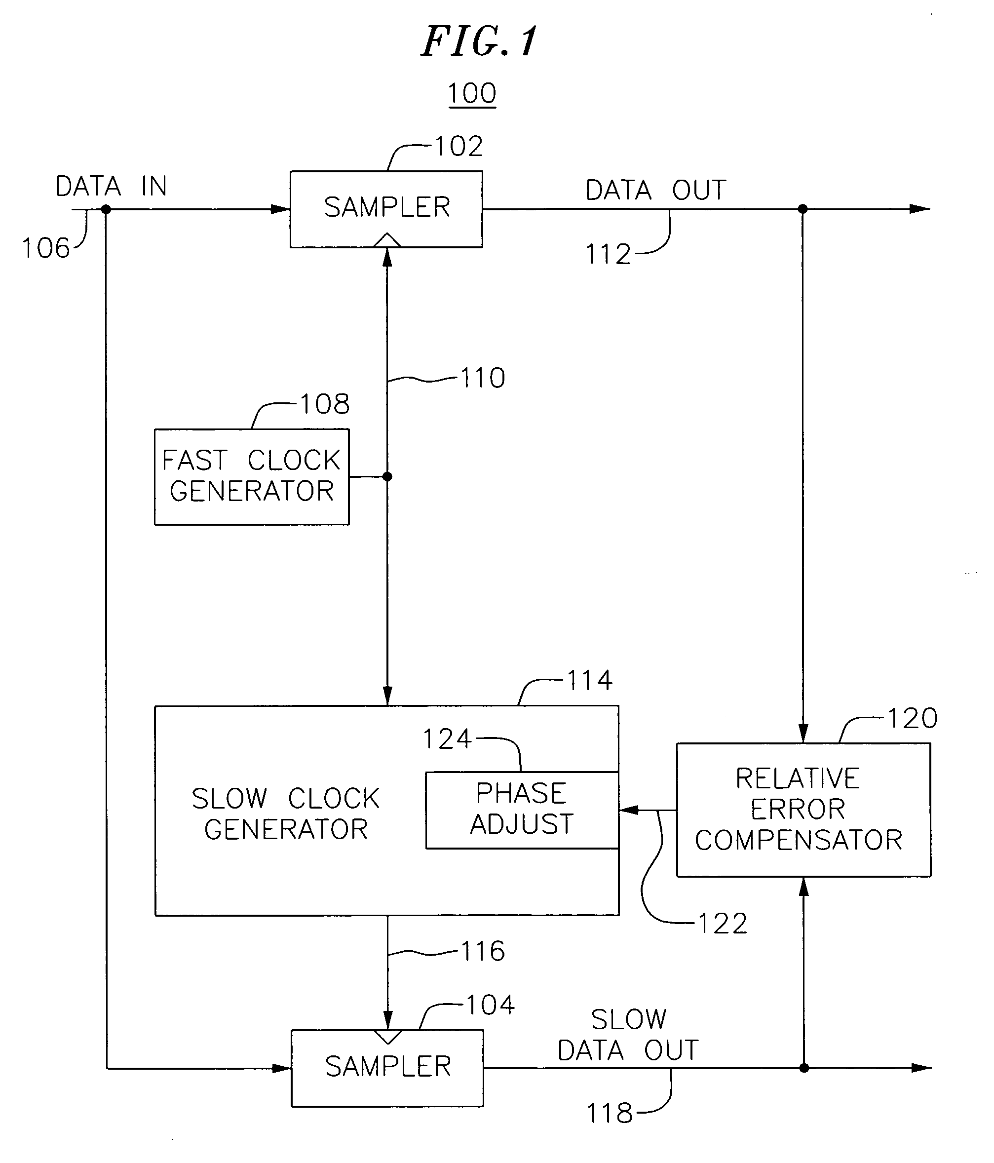
[0018]FIG. 1 is a simpli...


PUM


Abstract

A system may adjust the times at which data is sampled by separate sampling mechanisms. Here, it may be desirable to ensure that one sampler samples data at substantially the same time as the other sampler. For example, output data from a high speed sampler that samples received data may be compared with an output of an analog to digital converter that samples the received data at a lower data rate. This difference or relative error may be accumulated over a period of time for given values of delay applied to the clock for the analog to digital converter. In this way, a delay value that minimizes the relative error may be selected as a desired delay value.

Description

TECHNICAL FIELD [0001] This application relates to data communications and, more specifically, to a system and method for adjusting delay in a circuit in accordance with relative error measurements. BACKGROUND [0002] Conventional receivers for high speed serial communication systems may include a clock and data recovery circuit that extracts clock and data information from a received serial signal. For example, such a circuit may produce a clock signal synchronized with the incoming signal and the clock signal may then be used to recover data (e.g., data symbols) from the signal. Typically, the clock signal is generated at a frequency that matches the frequency of the data symbol rate in the received signal. The clock signal is then used to sample the received signal to recover individual data bits that correspond to each data symbol. [0003] A clock and data recovery circuit may comprise a phase lock loop (“PLL”) or a delay lock loop (“DLL”) that aligns the edges, for example the ri...

Claims


Application Information

Patent Timeline
Patent Type & Authority Applications(United States)
IPC IPC(8): G06F11/00
CPCH03L7/0814H03L7/087H03L7/10H04L25/03146H04L7/0058H04L7/033H03M1/1245H03L7/1075
Inventor MOMTAZ, AFSHIN
Owner AVAGO TECH INT SALES PTE LTD
Why Eureka
Try Eureka