Multi cyclone dust-collecting apparatus

a dust-collecting apparatus and multi-cyclone technology, applied in the direction of vortex flow apparatus, cleaning equipment, separation process, etc., can solve the problems of inability to achieve optimal dust-collecting efficiency, and inability to completely separate out fine dirt particles, etc., to achieve the effect of improving the dust-collecting efficiency

Inactive Publication Date: 2006-11-16
SAMSUNG GWANGJU ELECTRONICS CO LTD
View PDF8 Cites 188 Cited by
  • Summary
  • Abstract
  • Description
  • Claims
  • Application Information

AI Technical Summary

Benefits of technology

[0012] The present invention has been developed in order to solve the above problems in the related art. One aspect of the present invention is to provide a multi cyclone dust-collecting apparatus to increase the number of secondary cyclones in a limited space to improve a dust-collection efficiency. Another aspect of the present invention is to provide a multi cyclone dust-collecting apparatus having no limitation in arranging secondary cyclones and also changing the arrangement of the secondary cyclones according to the configurations of the vacuum cleaner and the cyclone dust-collecting apparatus. A third aspect of the present invention is to provide a multi cyclone dust-collecting apparatus having the capability of separating out very fine dirt particles, which are not still separated out by the secondary cyclones.

Problems solved by technology

The conventional dust-collecting apparatus mainly uses a dust filter, which requires frequent replacement and causes unpleasantness to a user in the replacement.
However, one problem with the cyclone dust-collecting apparatus is its inability to completely separate out fine dirt particles.
Therefore, an optimal dust-collection efficiency cannot be achieved and also there is a limitation to the designing of the cyclone dust-collecting apparatus.
Also, since the multi cyclone dust-collecting apparatus as described above cannot theoretically achieve the operation of completely separating out very fine dirt particles, a device having the capability of removing the very fine dirt particles completely is demanded.

Method used


Image

  • Multi cyclone dust-collecting apparatus
  • Multi cyclone dust-collecting apparatus
  • Multi cyclone dust-collecting apparatus

Examples


Embodiment Construction

[0039] Hereinafter, a multi cyclone dust-collecting apparatus according to embodiments of the present invention will now be described with the accompanying drawings.

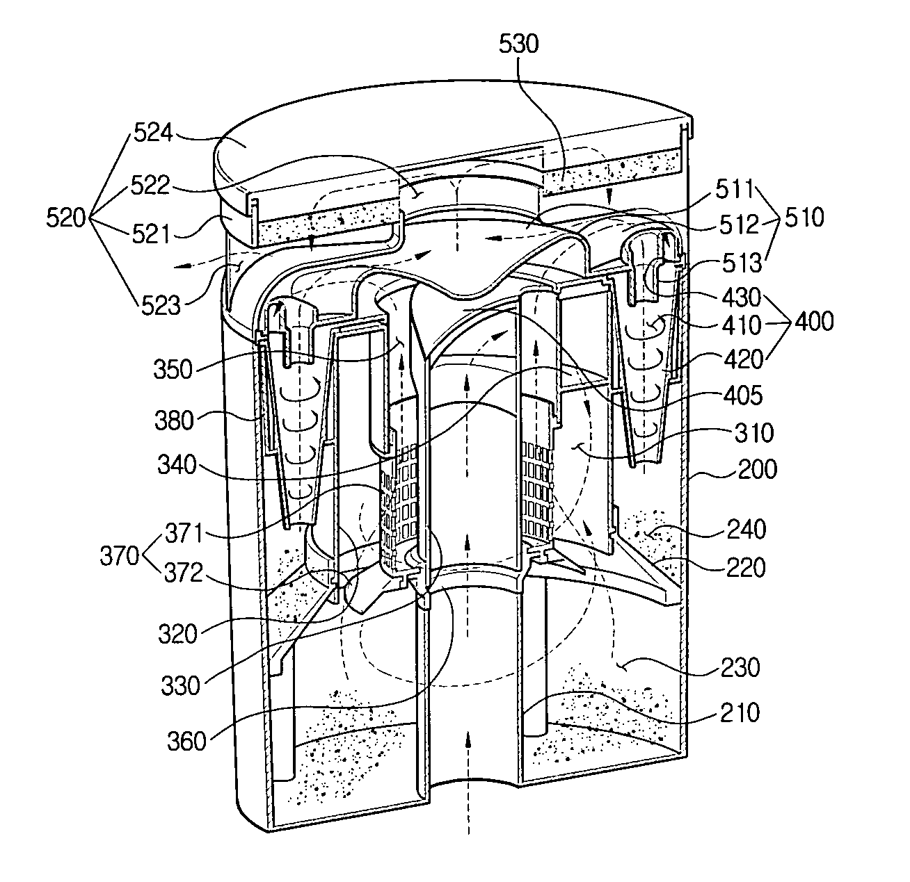
[0040] Referring to FIG. 3, a multi cyclone dust-collecting apparatus 100 comprises a dust-collecting housing 200, a first cyclone 300 disposed in the dust-collecting housing 200, a plurality of secondary cyclones 400 disposed in the dust-collecting housing 200 and arranged around an outer circumference of the first cyclone 300 at a certain interval, and a cover unit 500 disposed on the top the dust-collecting housing 200. On the first stage, the first cyclone 300 centrifugally separates out relatively large dirt particles included air drawn in from the outside, and on the second stage, the secondary cyclones 400 separate out fine dirt particles included in the air discharged from the first cyclone 300. The dust-collecting housing 200 collects dirt particles separated out from the air in the first and the second cyclone...


PUM

PropertyMeasurementUnit
Diameteraaaaaaaaaa
Heightaaaaaaaaaa
Circumferenceaaaaaaaaaa

Abstract

A multi cyclone dust-collecting apparatus including a dust-collecting housing; a first cyclone; a plurality of secondary cyclones; and a cover unit is provided. The dust-collecting housing has a suction pipe, which draws in ambient air. The first cyclone is disposed in the dust-collecting housing and has a first inlet port formed on a lower portion thereof to fluidly communicate with the suction pipe. The first inlet port and an air outlet port of the first cyclone have the same axis. The plurality of secondary cyclones are arranged outside the first cyclone at a predetermined interval and disposed in the dust-collecting housing. The cover unit guides the air discharged from the first cyclone to the respective secondary cyclones, filters again the air separated out from the dirt particles in the secondary cyclones, and discharges cleaned air outwardly.

Description

CROSS-REFERENCE TO RELATED APPLICATIONS [0001] This application claims benefit under 35 U.S.C. §119 from Korean Patent Application Nos. 2005-40756, filed May 16, 2005; and 2005-67917, filed Jul. 26, 2005, the entire contents of both of which are incorporated herein by reference.BACKGROUND OF THE INVENTION [0002] 1. Field of the Invention [0003] The present invention relates to a dust-collecting apparatus employed in a vacuum cleaner, and more particularly, to a multi cyclone dust-collecting apparatus for centrifugally separating and removing dirt from air drawn in a vacuum cleaner by performing several processes. [0004] 2. Description of the Related Art [0005] In general, a vacuum cleaner comprises a suction brush to draw dirt-entrained air from a cleaning surface, a dust-collecting apparatus to separate out the dirt particles from the air drawn in through the suction brush, and a suction motor serving as a driving source to generate a suction force. The conventional dust-collecting...

Claims


Application Information

Patent Timeline
IPC IPC(8): B01D45/12
CPCA47L9/1625A47L9/1641A47L9/165A47L9/1666B04C2009/002B04C5/02B04C5/185B04C5/24A47L9/1683
Inventor JEON, KYONG-HUI
Owner SAMSUNG GWANGJU ELECTRONICS CO LTD
Why Eureka
Try Eureka