
Method and apparatus for creating sacrificial patterns and cast parts

a technology of applied in the field of methods and apparatus for creating sacrificial patterns and cast parts, can solve the problems of increasing the complexity and cost of the process, severe limitations on the structural integrity of the mold, and limiting the geometry of the end product, i.e. the casting, and achieve the effect of removing sticky oxide residu

Inactive Publication Date: 2006-11-16
JOYNER VICTOR
View PDF22 Cites 24 Cited by
  • Summary
  • Abstract
  • Description
  • Claims
  • Application Information

AI Technical Summary

Benefits of technology

The present invention describes a way to make 3D objects using special materials that can be solidified when exposed to light. There are two types of material: those that conduct light and those that react inside the liquid material to cause its solidification. By using these materials in combination with clear plastic molds, researchers have created new methods for making complex objects without leaving any unwanted marks on their surfaces.

Problems solved by technology

This patent discusses different methods for directly casting objects using photosensitive materials (also called photopolymers). However, these existing methods have certain drawbacks. For one thing, they often require expensive equipment like special lighting fixtures or complicated processes involving multiple steps. Additionally, some methods result in incomplete curing of the object due to limited access to the backside of the mold. Other issues may arise if there are any unreacted components left behind in the final structure.

Method used


Image

  • Method and apparatus for creating sacrificial patterns and cast parts
  • Method and apparatus for creating sacrificial patterns and cast parts
  • Method and apparatus for creating sacrificial patterns and cast parts

Examples


Embodiment Construction

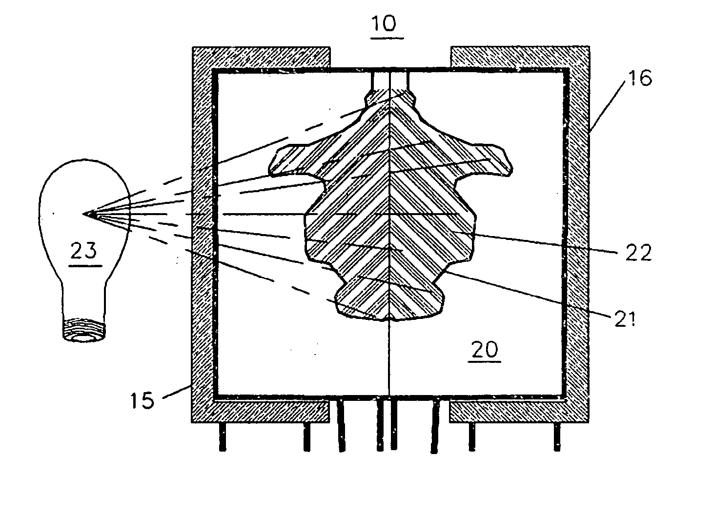
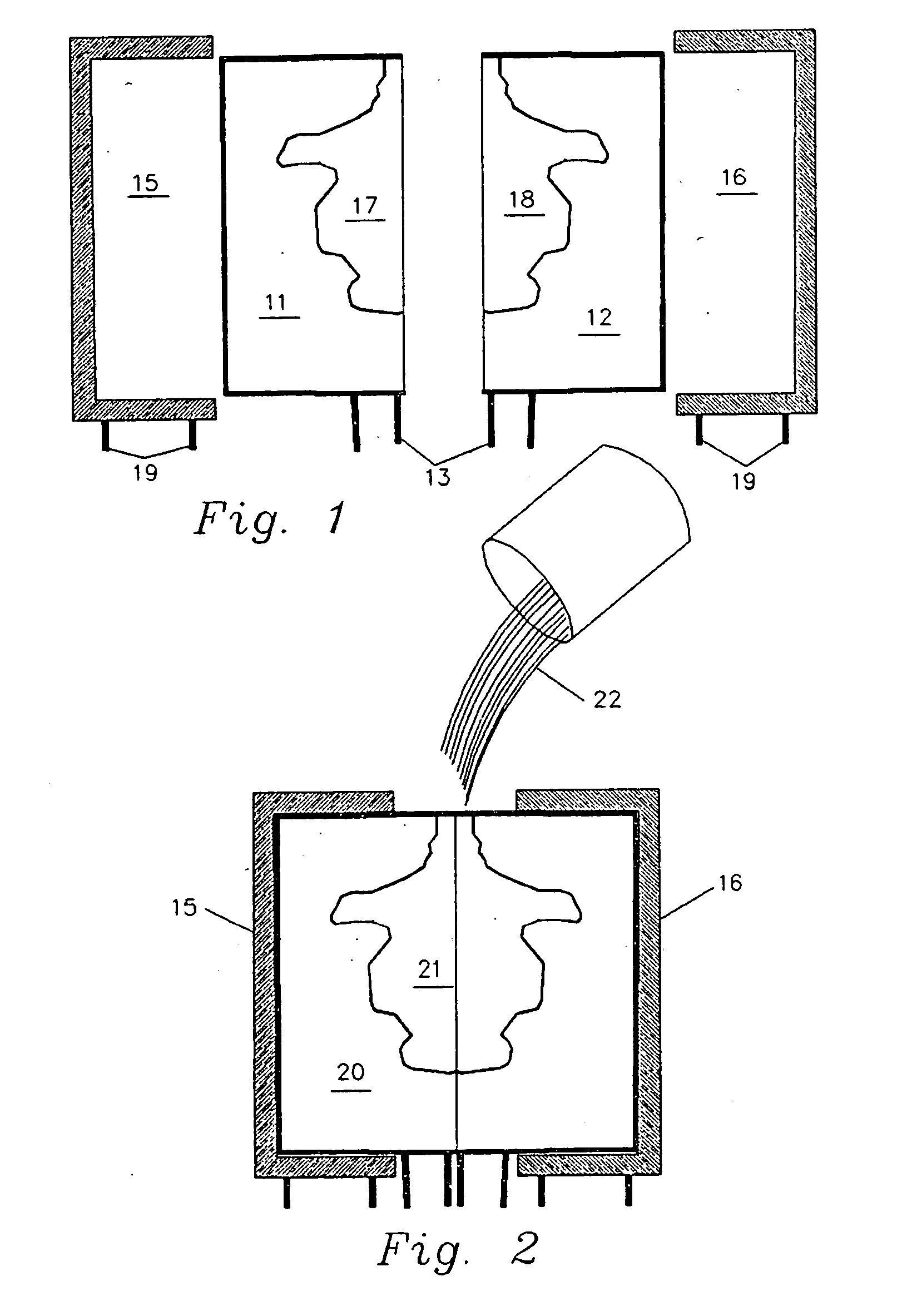
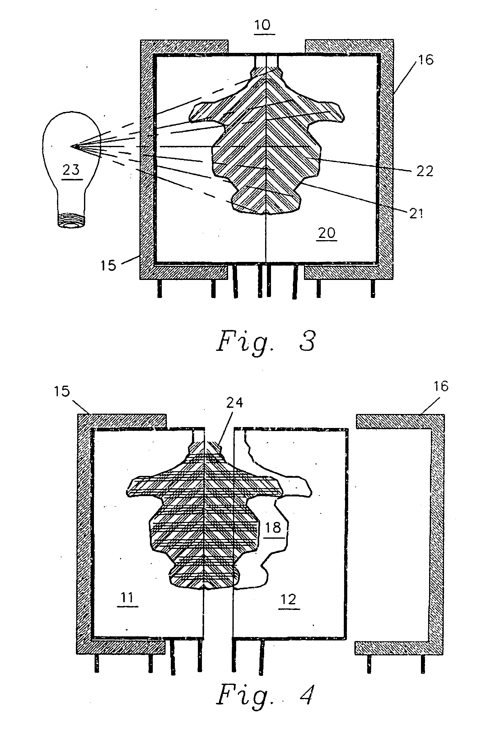
[0038] Throughout the following description and claims, the terms “cure”, “cured”, “curing”, “solidified”, “solidifying”, “hardening” and “hardened” are used interchangeably to describe a transition of material from liquid to solid. The term “radiation” is used to identify the radiation which initiates the transition of material, polymerization, from a liquid to a solid which may be soft, flexible, hard, ridged or solid having enhanced properties, such as having qualities that enhance its use as a sacrificial model in a lost wax process. The frequency of polymerization initiating radiation is dependent on the photo initiator or initiators used in the casting compound. They may respond to radiation ranging from radio frequencies through microwave, infrared, the visible spectrum and ultraviolet. In the preferred embodiment, the polymerization initiating radiation is in the ultraviolet blacklight range, 352 nanometers, for one radiation step and in the ultraviolet bluelight range, 368 ...


PUM

PropertyMeasurementUnit
Nanoscale particle sizeaaaaaaaaaa
Pressureaaaaaaaaaa

Abstract

A process and apparatus for casting three-dimensional parts and sacrificial models from a class of casting compounds which incorporate one or more radiation activated photo initiators which cause polymerization of the casting compound causing it to solidify or transition from a solid in a first state to a solid more suitable for use as a sacrificial model in a lost wax casting process. The class of casting compounds include, 1) compounds which act as conduits for the polymerization initiating radiation during and/or after hardening and 2) compounds which are hardened by a radiation induced chain reaction throughout the body of fluid casting compound. These compounds allow the part being cast to be cured within transparent molds that are supported by transparent mold frames. The apparatus consists of a radiation source positioned to irradiate the casting compound within a mold cavity through the mold frame and mold wall to effect the polymerization, solidifying, process. Separation of the molded part from the mold is enabled by the relative flexibility between the part and mold cavity walls. This is a function of using a soft, flexible material for the mold body and/or a polymerization process which caused the casting compound the solidify into a soft, flexible object. When the polymerized cast part is at least partially removed from the mold, it may be subjected to additional radiation of a frequency different form that initially applied the cause the solid cast part to transition to a hard or ridged part having properties more suitable for a model which is to be used as a sacrificial model in a lost wax process. An automated casting system is anticipated which is enabled by the use of very soft, stretchable and deformable material for the mold body and supporting the mold with radiation transparent mold frames. Oxygen and other gases in the atmosphere react with some casting compounds to create a sticky film on mold cavity walls which causes difficulty when removing a casting from a mold. This problem is eliminated by purging the mold cavity with an inert gas between casts.

Description


Claims


Application Information

Patent Timeline
Owner JOYNER VICTOR
Learn More