Bandpass filter and wireless communications equipment using same

a wireless communication and filter technology, applied in the field of bandpass filters, can solve the problems of dielectric filters failing to have a wide passband and small size at the same time, extending the bandwidth to be used as bandpass filters for wider frequency bands, and affecting the signal receiving sensitivity, so as to achieve wide passband communication, improve signal receiving sensitivity, and simple structur

Inactive Publication Date: 2006-11-16
KYOCERA CORP
View PDF4 Cites 25 Cited by
  • Summary
  • Abstract
  • Description
  • Claims
  • Application Information

AI Technical Summary

Benefits of technology

[0014] The bandpass filter with this structure allows the resonators located at the intermediate location to be electromagnetically coupled with each other. Because of this coupling, selecting an appropriate amount of capacitance for each resonator allows a bandpass filter to have a wide passband. In addition, providing a plurality of resonators enables the filter to have steep attenuation characteristics.
[0046] Another aspect of the present invention is wireless communications equipment including the foregoing bandpass filter. According to this wireless communications equipment, signal receiving sensitivity is improved, and wide passband communications and low power consumption can be realized, as well as mutual interference with other wireless communications equipment such as W-LAN can be prevented.

Problems solved by technology

Since bandwidths in these materials are determined depending on the electromechanical coupling coefficients of crystalline quartz and piezoelectric substrates, extending the bandwidths to be used as bandpass filters for wider frequency bands has been difficult when the material is taken into consideration.
However, in order to produce a dielectric filter so that it has a center frequency of 3.98 GHz, a bandwidth of 1.6 GHz, and attenuation of less than −30 dB at 2.48 GHz and 5.15 GHz where W-LAN operates, the size thereof is bound to be as large as about 10×3×1.5 mm, which is disadvantageous.
Dielectric filters thus fail to have a wide passband and small size at the same time.

Method used


Image

  • Bandpass filter and wireless communications equipment using same
  • Bandpass filter and wireless communications equipment using same
  • Bandpass filter and wireless communications equipment using same

Examples


example

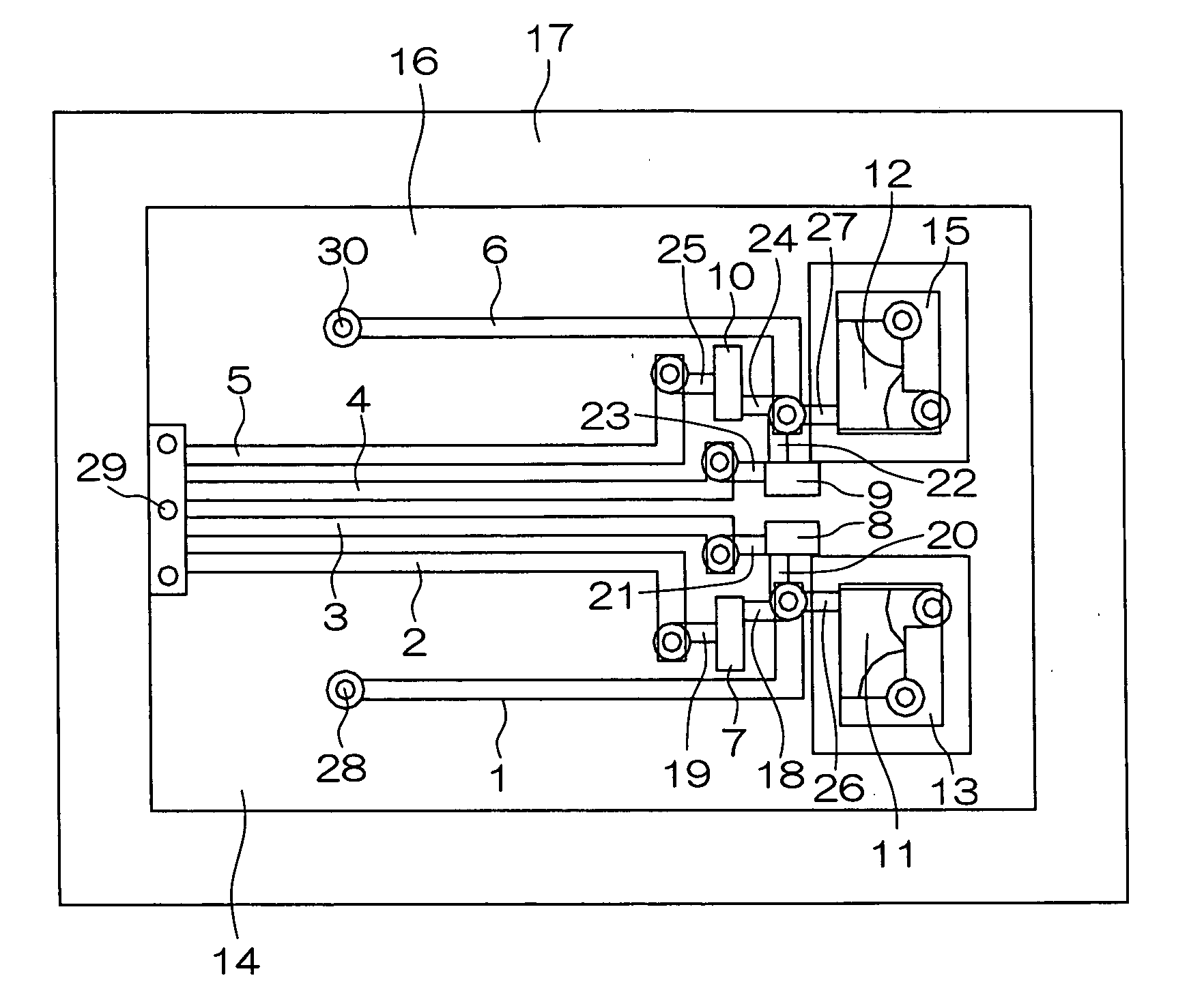
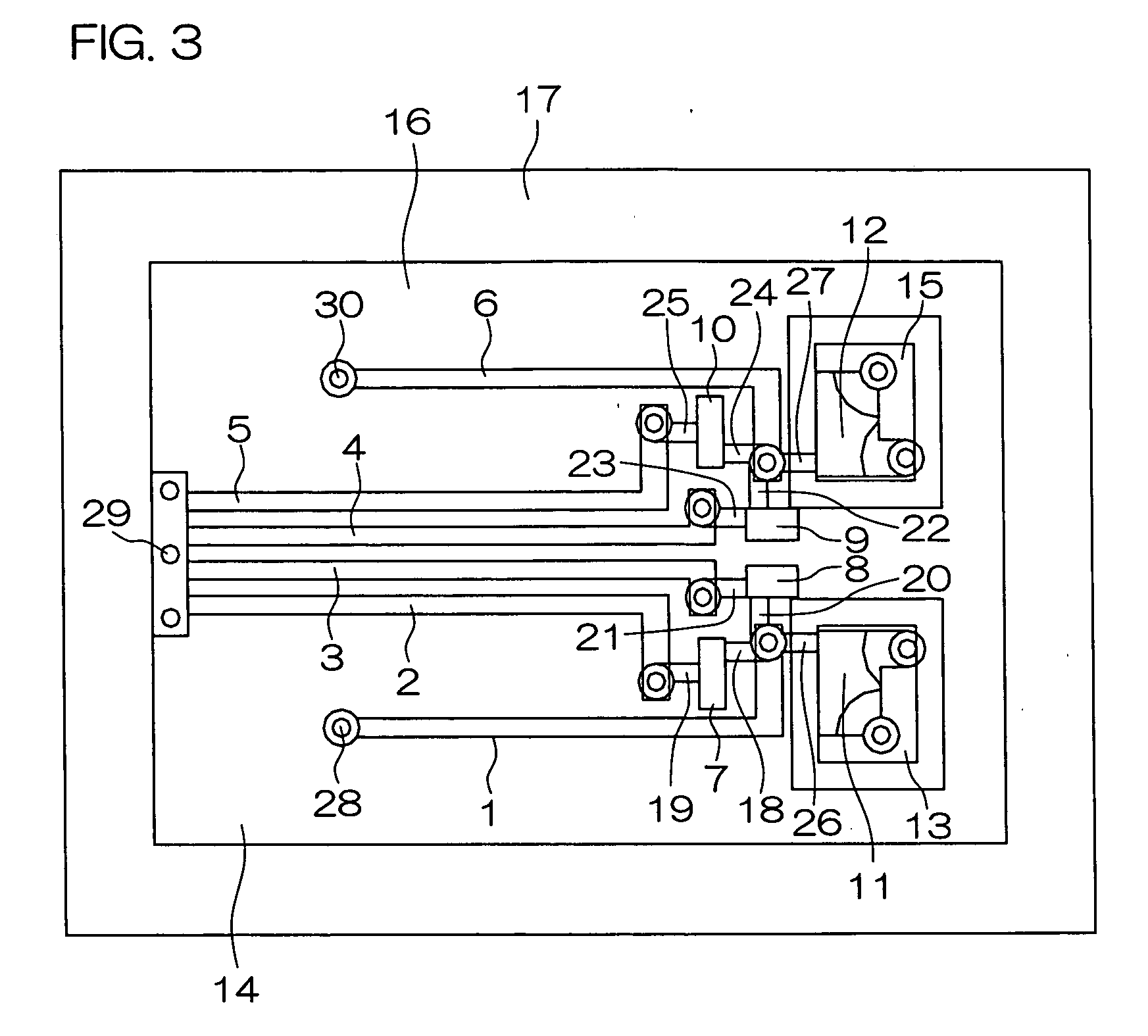
[0168] A bandpass characteristic S21 and a reflection characteristic S11 of a bandpass filter fabricated with wiring patterns shown in FIGS. 4A-4H and FIGS. 5A-5E were measured using the vector network analyzer 8719ES produced by Agilent Technologies.

[0169] In this case, ceramics with a dielectric coefficient of 9.0 was used, and the dielectric layers consisted of twelve layers and the thickness of each of the dielectric layers was 75 um. The size of the dielectric was 4.5×3.2 mm. The measured bandpass characteristic S21 and reflection characteristic S11 are shown as a graph in FIG. 10.

[0170] In addition, with the conditions being the same, a bandpass characteristic S21 and a reflection characteristic S11 of a bandpass filter additionally comprising a conductor pattern 99 shown in FIGS. 8A-8E, in which the input terminal electrode and output terminal electrode were connected through an input / output capacitance C11 were measured. The results of this are shown in FIG. 11.

[0171] Acc...


PUM


Abstract

Disclosed is a bandpass filter comprising a first resonator 1 to a sixth resonator 6 having lengths of basically ¼ wavelength, an input section IN connected to an ungrounded end of the first resonator, and an output section OUT connected to an ungrounded end of the sixth resonator, wherein the second to fifth resonators 2-5 are electromagnetically coupled with each other, the second and the third resonators are respectively coupled to the first resonator via the first and the second capacitances C1,C2, the third and the fourth resonators are respectively coupled to the sixth resonator via the third and the fourth capacitances C3,C4, and the input section IN and output section OUT are coupled to the first resonator and sixth resonator through an input and output capacitances C5, C6, respectively. This bandpass filter can be a small size, low loss filter suitable for UWB (Ultra Wide Band).

Description

BACKGROUND OF THE INVENTION [0001] 1. Field of the Invention [0002] The present invention relates to a bandpass filter with wide bandpass characteristics and steep attenuation characteristics which is used suitably for UWB (Ultra Wide Band) in the wireless communications field, and communications equipment using the bandpass filter. UWB is expected to be utilized as a data transmitting medium for PC peripheral equipment such as external storage devices, printers and scanners, or as a data communications medium for digital TVs, projectors, digital steel cameras, digital video cameras, etc. [0003] 2. Description of the Related Art [0004] In recent years, attention is being given to UWB as a means of communications. This UWB is different from wireless local area network (herein after referred to as “W-LAN”) in communication length and data transmission rate. [0005] According to IEEE802.11.b, one of the standards for W-LAN, the communication length is 30-100 m, transmission power is 500...

Claims


Application Information

Patent Timeline
Patent Type & Authority Applications(United States)
IPC IPC(8): H01P1/203
CPCH01P1/20345H01P1/20
Inventor NINOMIYA, HIROSHINAKAMATA, KATSUROU
Owner KYOCERA CORP
Why Eureka
Try Eureka