Method to fabricate side shields for a magnetic sensor

a magnetic sensor and side shield technology, applied in nanoinformatics, instruments, record information storage, etc., can solve the problems of inhibiting the reduction of the read track width of the sensor, the noise in the sensor signal, etc., to improve the current flow of the sensor, and improve the mr sensor.

Inactive Publication Date: 2006-11-16
WESTERN DIGITAL TECH INC
View PDF10 Cites 259 Cited by
  • Summary
  • Abstract
  • Description
  • Claims
  • Application Information

AI Technical Summary

Benefits of technology

[0008] It is an advantage of the method for fabricating a magnetic head of the present invention that an improved MR sensor is created.
[0010] It is a further advantage of the method for fabricating a magnetic head of the present invention that an MR sensor having improved magnetic side shields is created.
[0011] It is yet another advantage of the method for fabricating a magnetic head of the present invention that an improved MR sensor having draped side magnetic shields and improved sensor current flow is created.
[0012] It is yet a further advantage of the method for fabricating a magnetic head of the present invention that an MR sensor having a decreased read track width and improved sensor current flow is created.

Problems solved by technology

As a result, the MR sensors must be fabricated with a reduced read track width, and stray magnetic shields from more closely spaced adjacent data tracks can generate noise in the sensor signals.
Current methods to create such draped shield MR sensors have certain drawbacks, as described herebelow, which inhibit the reduction of the read track width of the sensor.

Method used


Image

  • Method to fabricate side shields for a magnetic sensor
  • Method to fabricate side shields for a magnetic sensor
  • Method to fabricate side shields for a magnetic sensor

Examples


Embodiment Construction

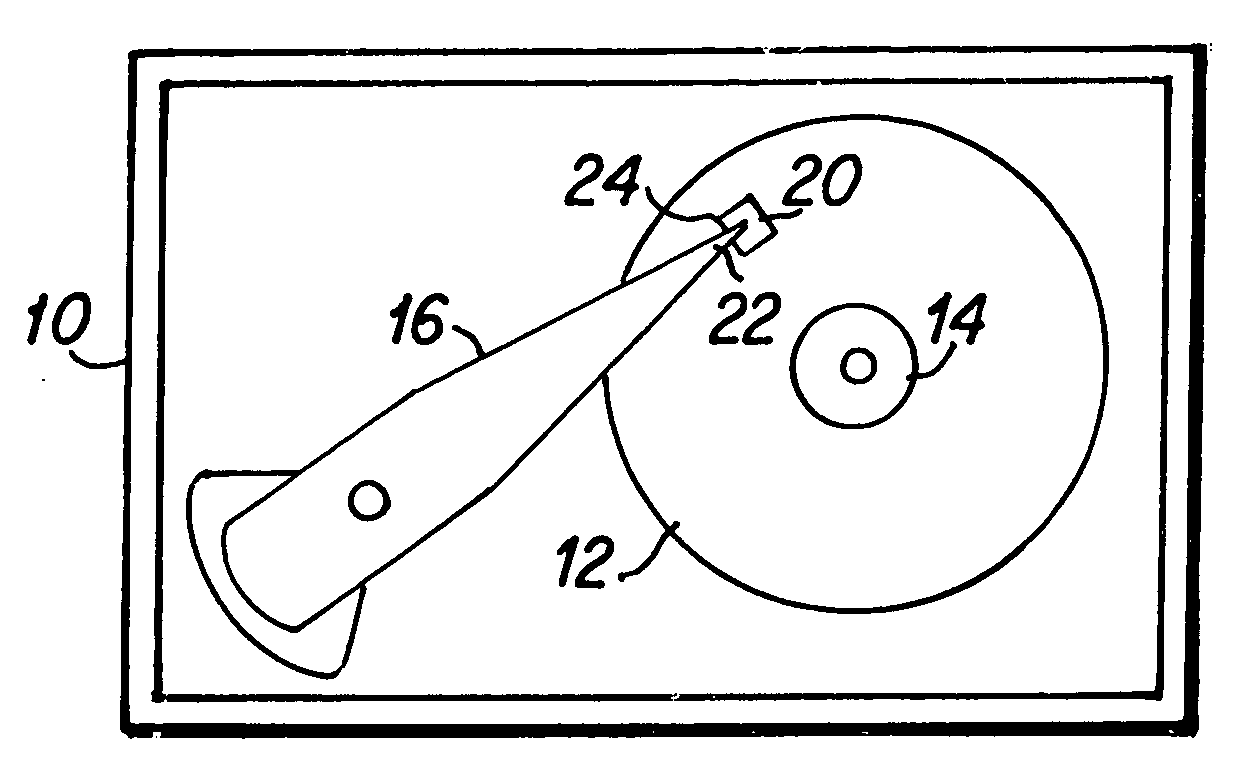
[0019]FIG. 1 is a top plan view that depicts significant components of a hard disk drive which includes the magnetic head of the present invention. The hard disk drive 10 includes a magnetic media hard disk 12 that is rotatably mounted upon a motorized spindle 14. An actuator arm 16 is pivotally mounted within the hard disk drive 10 with a slider 24 including a magnetic head 20 of the present invention disposed upon a distal end 22 of the actuator arm 16. A typical hard disk drive 10 may include a plurality of disks 12 that are rotatably mounted upon the spindle 14 and a plurality of actuator arms 16 each having one or more sliders 24 mounted upon the distal end 22 of the actuator arms. As is well known to those skilled in the art, when the hard disk drive 10 is operated, the hard disk 12 rotates upon the spindle 14 and the slider 24 with the magnetic head 20 acts as an air bearing that is adapted for flying above the surface of the rotating disk. The slider 24 includes a substrate ...


PUM

PropertyMeasurementUnit
thicknessaaaaaaaaaa
thicknessaaaaaaaaaa
thicknessaaaaaaaaaa

Abstract

A method for fabricating magnetic side shields for an MR sensor of a magnetic head. Following the deposition of MR sensor layers, a first DLC layer is deposited. Milling mask layers are then deposited, and outer portions of the milling mask layers are removed such that a remaining central portion of the milling mask layers is formed having straight sidewalls and no undercuts. Outer portions of the sensor layers are then removed such that a relatively thick remaining central portion of the milling mask resides above the remaining sensor layers. A thin electrical insulation layer is deposited, followed by the deposition of magnetic side shields. A second DLC layer is deposited and the remaining mask layers are then removed utilizing a chemical mechanical polishing (CMP) liftoff step. Thereafter, the first DLC layer and the second DLC layer are removed and a second magnetic shield layer is then fabricated thereabove.

Description

BACKGROUND OF THE INVENTION [0001] 1. Field of the Invention [0002] The present invention relates generally to spin valve sensors for magnetic heads, and more particularly to an improved tunnel valve MR sensor having a draped second magnetic shield. [0003] 2. Description of the Prior Art [0004] Magnetic heads for hard disk drives typically have a read head portion including a magnetoresistive (MR) spin valve sensor structure for reading data from the disk of the hard disk drive. As is well known to those skilled in the art, such MR sensor structures include a plurality of thin film layers disposed between two magnetic shields that define the read gap. The thin film layers have particular magnetic properties, and are sensitive to the magnetic field of the data bits on the hard disk. [0005] Recently developed read heads may use a tunnel junction sensor, also known as a “tunnel valve”, abbreviated “TV”, for reading the magnetic data bit signals from the hard disk. The TV sensor typical...

Claims


Application Information

Patent Timeline
Patent Type & Authority Applications(United States)
IPC IPC(8): G11B5/33
CPCB82Y10/00G11B5/112G11B5/3169Y10T29/49041G11B5/3909Y10T29/49044Y10T29/49046G11B5/3906
Inventor ARAKI, SATORUBEACH, ROBERT STANLEYCYRILLE, MARIE-CLAIREJAYASEKARA, WIPUL PEMSIRILE, QUANGLI, JUI-LUNGSEAGLE, DAVID JOHNZOLLA, HOWARD GORDON
Owner WESTERN DIGITAL TECH INC
Why Eureka
Try Eureka