
Hydraulic pump or hydraulic motor having a rotation speed sensor

a technology of rotation speed sensor and hydraulic motor, which is applied in the direction of pump parameters, positive displacement liquid engines, machines/engines, etc., can solve the problems of insufficient space for the rotation speed sensor and its fixing parts, not always the desired amount of space available, and increase production and assembly complexity. , to achieve the effect of space-saving solution

Inactive Publication Date: 2006-11-16
SAUER DANFOSS NORDBERG
View PDF16 Cites 7 Cited by
  • Summary
  • Abstract
  • Description
  • Claims
  • Application Information

AI Technical Summary

Benefits of technology

[0005] The present invention aims to provide a hydraulic pump or a hydraulic motor having improved rotation speed sensing.
[0007] The hydraulic pump or the hydraulic motor according to the invention has a rotating shaft, which is mounted in a fixed position in a housing and on which a pulse generator is provided. A rotation speed sensor, which is fixed to the housing, comprises a sensor element, which is associated with the pulse generator and fitted eccentrically and offset with respect to the insertion axis of the rotation speed sensor. It is thus possible for the outwardly leading main part of the rotation speed sensor to be displaced into a region where there is free space available in the housing variants in question, while the sensor element can be fitted within the housing with optimum proximity and alignment with respect to the pulse generator. This makes sensing of the rotation speed possible even in regions within the housing of hydraulic pumps and motors which are otherwise not accessible or are only accessible with difficulty.
[0010] It is advantageous if the first limb, bearing the sensor element, of the L-shaped rotation speed sensor is considerably longer than the second, outwardly pointing limb. The design engineer therefore has additional freedom in optimizing the offset of the sensor element with respect to the insertion axis and the process of passing the plug part through the housing wall and fixing it. The first limb of the L-shaped rotation speed sensor in this case preferably comprises a printed circuit board, which bears the sensor element and makes a particularly space-saving solution possible. The second limb of the rotation speed sensor is designed such that it closes off the wall of the housing in a sealing manner once it has been installed in said housing. The connection to the outside takes place merely via the plug connection. Components which protrude far out of the pump contour and are thus unprotected are avoided.

Problems solved by technology

Owing to the different installation conditions of the machines, there is not always the desired amount of space available for this.
There is then no longer sufficient space available for the rotation speed sensor and its fixing parts in order to be able to mount it perpendicularly with respect to the shaft along an axis parallel to the attachment flange.
This means additional complexity in terms of production and assembly.

Method used


Image

  • Hydraulic pump or hydraulic motor having a rotation speed sensor
  • Hydraulic pump or hydraulic motor having a rotation speed sensor
  • Hydraulic pump or hydraulic motor having a rotation speed sensor

Examples


Embodiment Construction

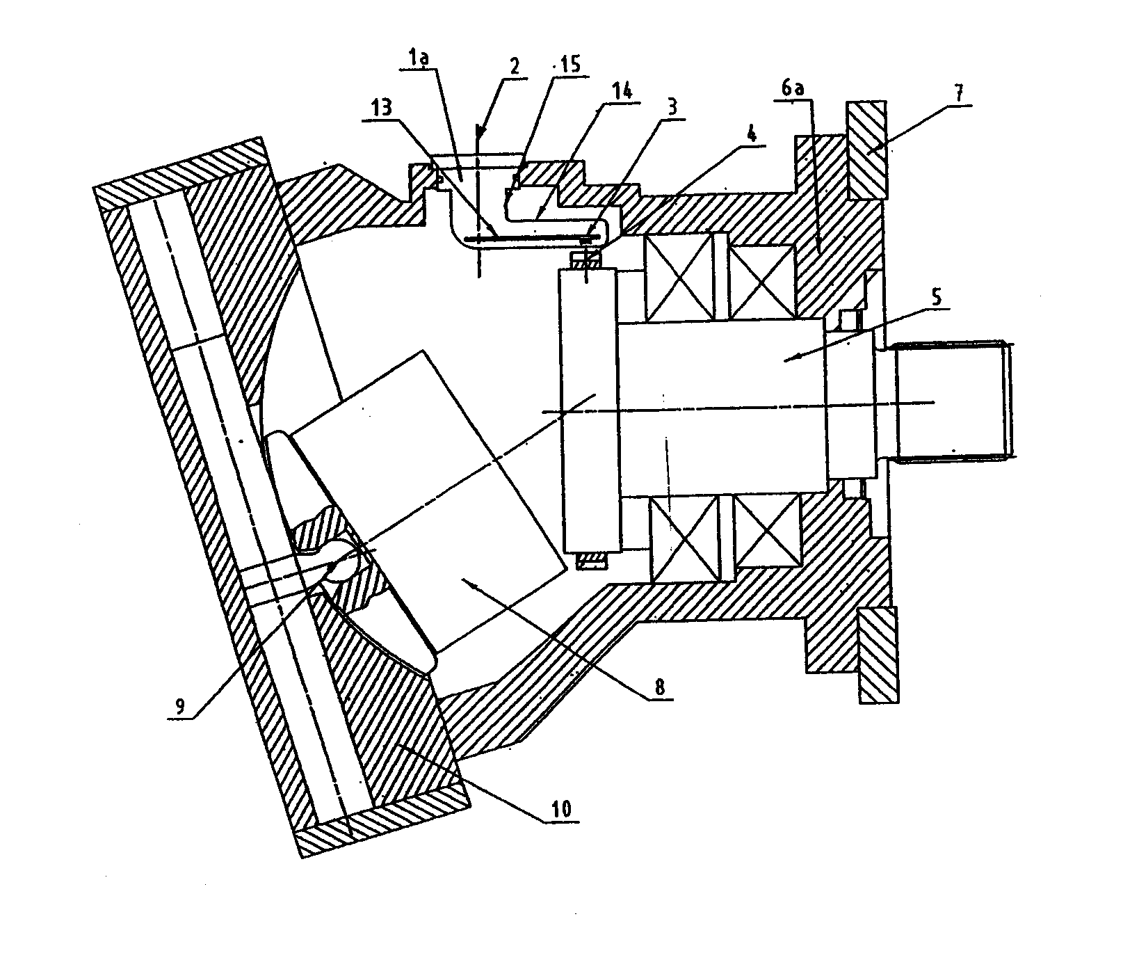
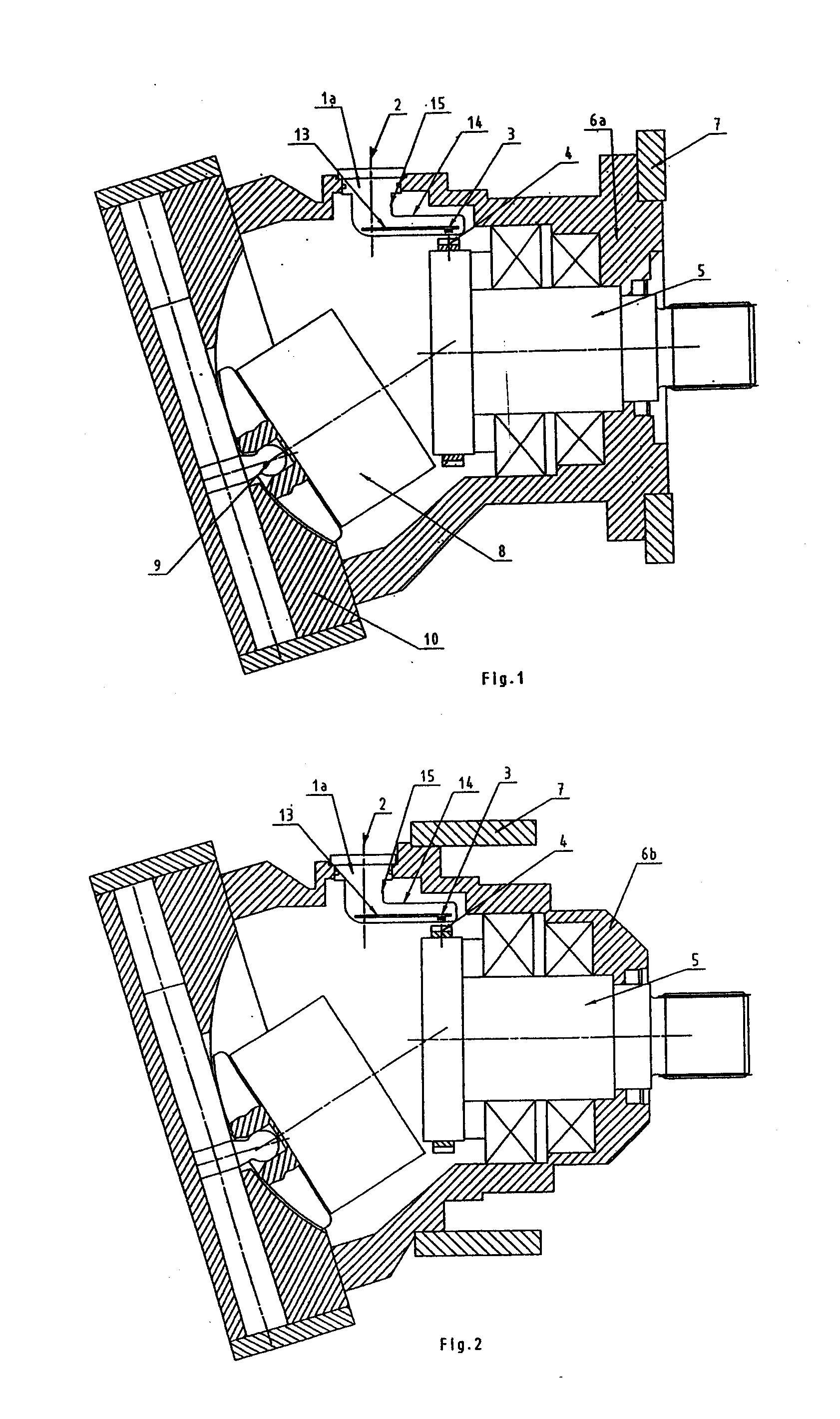
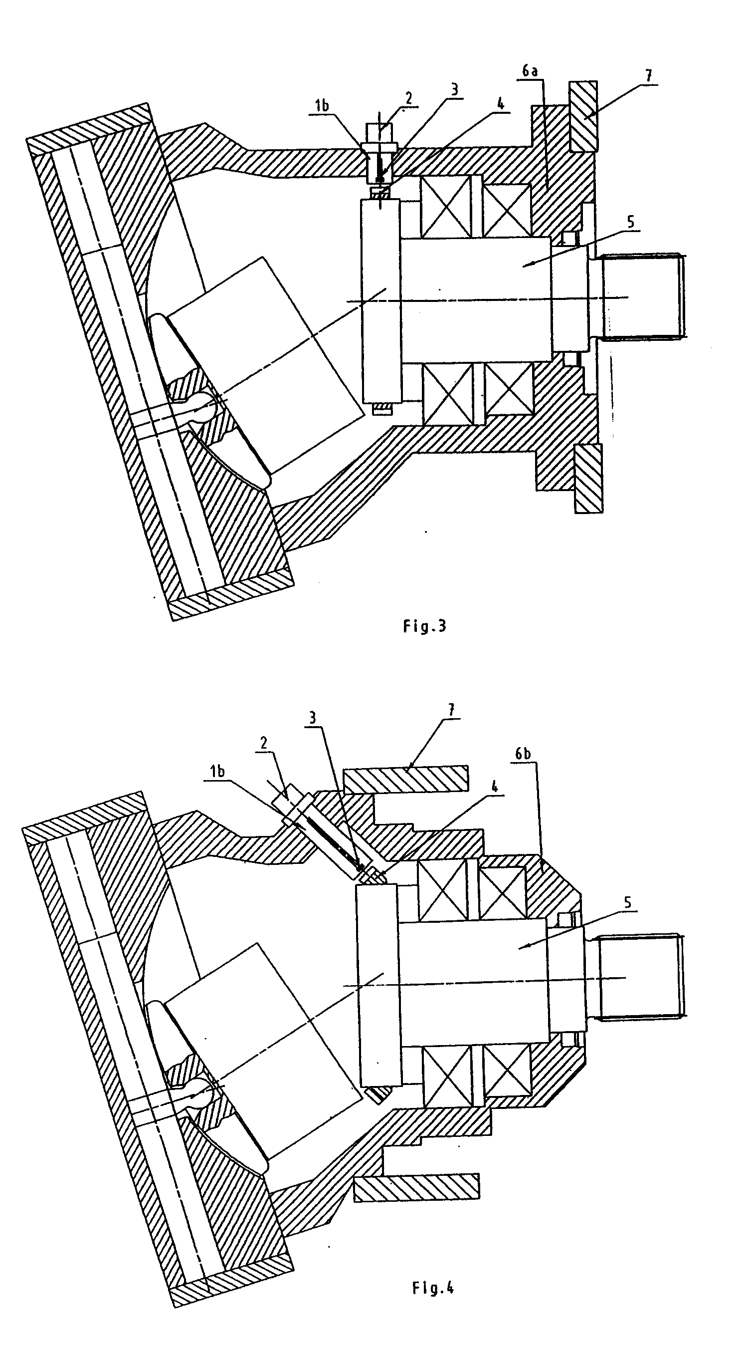
[0018]FIG. 1 illustrates an inclined-axis motor having a first housing variant 6a, in which the rotation speed sensor 1a according to the invention is installed. The housing 6a is connected to the gear mechanism 7 via a flange, only housing parts of said gear mechanism 7 being indicated here. The drive mechanism of the inclined-axis motor comprises in a known manner a cylinder block 8 and a pivoting mechanism 9, which are arranged in the region of the end housing 10.

[0019] The rotation speed is tapped off from the shaft 5, which is mounted in a fixed position in the housing 6a and on which an annular, magnetic pulse generator 4 is fixed, said pulse generator 4 producing corresponding pulses in the sensor element 3, a Hall probe, on rotation of the shaft 5. The Hall probe 3 is arranged on a printed circuit board 13, which extends along a first limb 14 of the L-shaped rotation speed sensor 1a. The limb 14 requires very little physical space. It can be matched optimally to the free sp...


PUM


Abstract

The invention relates to a hydraulic pump or hydraulic motor having a rotating shaft, which is mounted in a fixed position in a housing and on which a pulse generator is provided, and having a rotation speed sensor, which is fixed to the housing and comprises a sensor element associated with the pulse generator, the sensor element being fitted eccentrically and offset with respect to the insertion axis of the rotation speed sensor.

Description

BACKGROUND OF THE INVENTION [0001] The invention relates to a hydraulic pump or hydraulic motor having a rotation speed sensor in accordance with the features of claim 1. Such hydraulic machines, which are used as a pump or a motor, have a rotating shaft, which is mounted in a fixed position in the housing, and a device for the purpose of determining its speed of revolution, which is required, for example, in the case of inclined-axis motors for the detection of the vehicle speed. In this case, the rotation speed is tapped off from the rotating parts via a sensor, in which case annular gears or magnet rings are often used which are fitted to the rotating parts and have the task of producing pulses for a sensor fixed to the housing. [0002] The shaft is an option for the positioning of the pulse generator. The sensor in this case needs to be provided opposite on the housing. Owing to the different installation conditions of the machines, there is not always the desired amount of space...

Claims


Application Information

Patent Timeline
Patent Type & Authority Applications(United States)
IPC IPC(8): F04B27/08
CPCF04B1/122F04B2201/1208F04B2201/1201F04B1/2014
Inventor REIMER, MARKUS
Owner SAUER DANFOSS NORDBERG
Learn More