Distributor system for downflow reactors

a technology of distribution system and reactor, which is applied in the direction of liquid-gas reaction process, chemical/physical/physico-chemical process, chemical apparatus and processes, etc., can solve the problem of not optimally mixing gas and liquid and achieve the effect of improving uniformity across the horizontal cross section

Active Publication Date: 2006-11-16
TOPSOE AS
View PDF8 Cites 22 Cited by
  • Summary
  • Abstract
  • Description
  • Claims
  • Application Information

AI Technical Summary

Benefits of technology

[0004] It is therefore an objective of the invention to provide an improved uniformity across the horizontal cross section of a reactor in the flow descending from the chimneys and improved mixing of the gas and liquid entering the second distributor tray prior to contact with the subsequent catalyst bed.
[0005] It is another object of the invention to be able to provide for such improved uniformity in the flow and mixing of the gas and liquid while at the same time keeping intact the swirling motion effected in the mixing chamber above the chimneys.

Problems solved by technology

Accordingly, the downward flow from the chimneys is unevenly distributed in the second (final) distributor tray, with the attendant effect that the gas and liquid are not optimally mixed across the horizontal cross section of the reactor when contacting the underlying catalyst bed.

Method used


Image

  • Distributor system for downflow reactors
  • Distributor system for downflow reactors
  • Distributor system for downflow reactors

Examples


Embodiment Construction

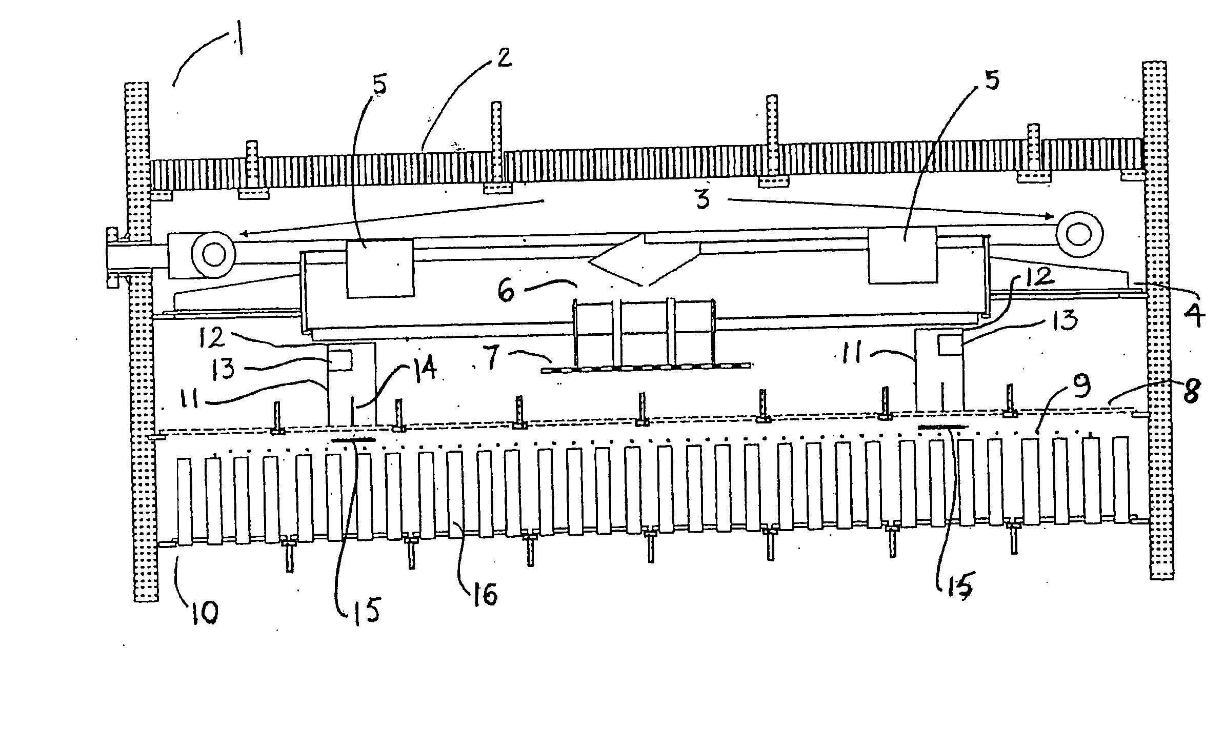
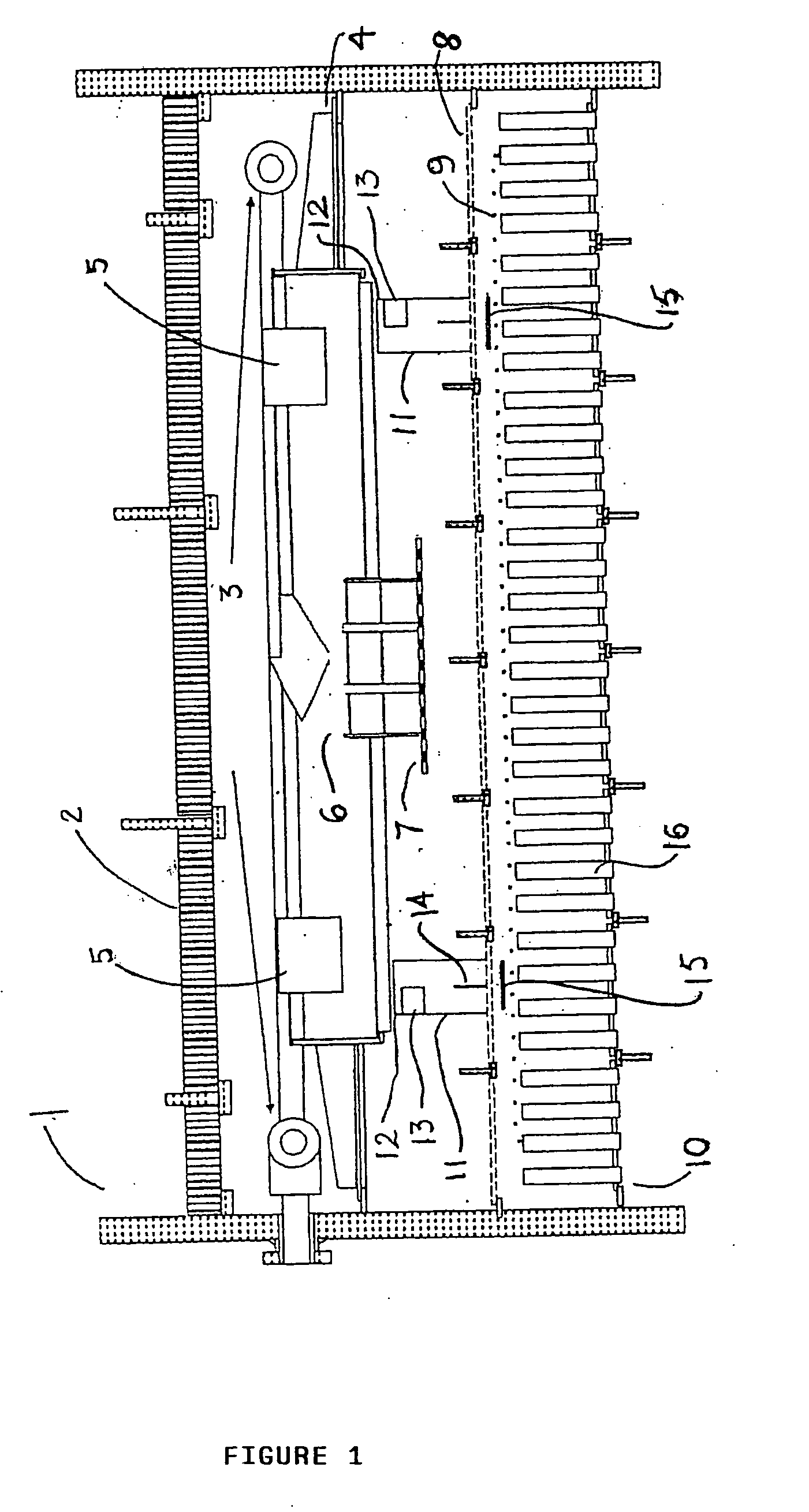
[0023] Referring to FIG. 1, the downflow reactor 1 comprises a quench section below a catalyst tray 2 having a quench ring 3 for injection of quench gas, normally hydrogen, collector tray 4 arranged below said quench ring, spillways 5, vortex mixing chamber 6, impingement plate 7, first distributor tray 8, perforated plate 9, and a second or final tray 10 in the form of a vapour lift tube (VLT) redistribution tray.

[0024] A pool of liquid accumulates in collector tray 4 and is transferred to spillways 5, which are provided with outlets that impart a rotary movement to the exiting fluid. The vortex mixing chamber 6 mixes the reactant fluids in a compartment where the fluids are swirled together. The fluids exit the mixing chamber 6 by overflow in a weir and pass through a central orifice at the bottom. The fluids then drop onto the impingement plate 7, which redirects the flow radially underneath the mixing chamber 6. The impingement plate 7 is located at a distance above the first d...


PUM


Abstract

Downflow catalytic reactor having a plurality of catalyst beds in which a mixture of gas and liquid are passed, the region in between subsequent catalyst beds being provided with a distributor system for the distribution and mixing of gas and liquid prior to contact with a subsequent catalyst bed, said region comprising: (a) gas injection line arranged below a catalyst support tray, (b) collector tray adapted to receive gas and liquid, (c) spillway collectors extending above the level of said collecting tray, (d) mixing chamber adapted to receive the gas and liquid descending from said spillway collectors, (e) impingement plate below said mixing chamber, (f) first distributor tray arranged below said impingement plate having a number of apertures throughout and a number chimneys, and (g) second distributor tray arranged below said first distributor tray for the redistribution of gas and liquid prior to contact with the subsequent catalyst bed, wherein the at least one chimney is provided with a distributor device that is able to divide the chimney chamber into at least two chambers.

Description

BACKGROUND OF THE INVENTION [0001] This invention relates to a distributor device for improving the distribution and mixing of gas and liquid in the region between catalyst beds in downflow catalytic reactors comprising a plurality of said beds. More particularly, the invention relates to a distributor device for improving the distribution and mixing of gas and liquid entering the final distributor plate above the top of a succeeding catalyst bed. The distributor device is particularly suitable for catalytic reactors in which gas-liquid mixtures are passed through beds of solid catalyst particles, particularly for downflow catalytic reactors used for hydrotreating and hydrocracking in oil refining operations. [0002] In downflow reactors it is necessary that gas and liquid are properly mixed across the horizontal cross section of the reactor prior to entering the catalyst beds. A plurality of catalyst beds is arranged within the reactor and a distributor system for the proper mixing ...

Claims


Application Information

Patent Timeline
Patent Type & Authority Applications(United States)
IPC IPC(8): B01J8/04B01J10/00
CPCB01J8/008B01J2219/24B01J8/0257B01J8/0278B01J8/04B01J8/0453B01J8/0492B01J19/0053B01J19/24B01J19/26B01J2208/00548B01J2208/0061B01J2208/00831B01J2208/00849B01J2208/02B01J2219/00024B01J2219/00164B01J2219/00182B01J2219/00761B01J2219/182B01J8/02B01J8/00
Inventor BREIVIK, RASMUSMOGENSEN, JOHANHANSEN, TORKIL OTTESEN
Owner TOPSOE AS
Why Eureka
Try Eureka