
Injection device

a technology of injection device and needle, which is applied in the direction of intravenous device, other medical devices, infusion needles, etc., can solve the problems of unguaranteed safe removal of needles and the difficulty of much greater inherent weight, and achieve the effect of manipulating an injection devi

Inactive Publication Date: 2006-11-16
BAYER INTELLECTUAL PROPERTY GMBH
View PDF2 Cites 171 Cited by
  • Summary
  • Abstract
  • Description
  • Claims
  • Application Information

AI Technical Summary

Benefits of technology

[0003] The object of the invention is to make the handling of an injection device after completion of the injection easier and safer.
[0007] After the injection has been completed, the needle does not protrude from the injection device, and for this reason there is also no longer any risk of injury when handling the injection device after the injection.
[0008] If the protective cap is removed following insertion of the syringe, and if the protective cap is put back on again after the injection procedure, and before removal of the syringe, then the patient at no time sees the needle, neither before nor after the injection, in the case of a prefilled syringe, a fact which facilitates handling of the injection device, particularly for those patients who suffer from what is called “needle phobia”.

Problems solved by technology

In the known devices, this is not guaranteed.
On the contrary, in extreme cases, safe removal of the needle is made even more difficult by the much greater inherent weight of the injection device compared to a syringe.

Method used


Image

  • Injection device
  • Injection device
  • Injection device

Examples


Embodiment Construction

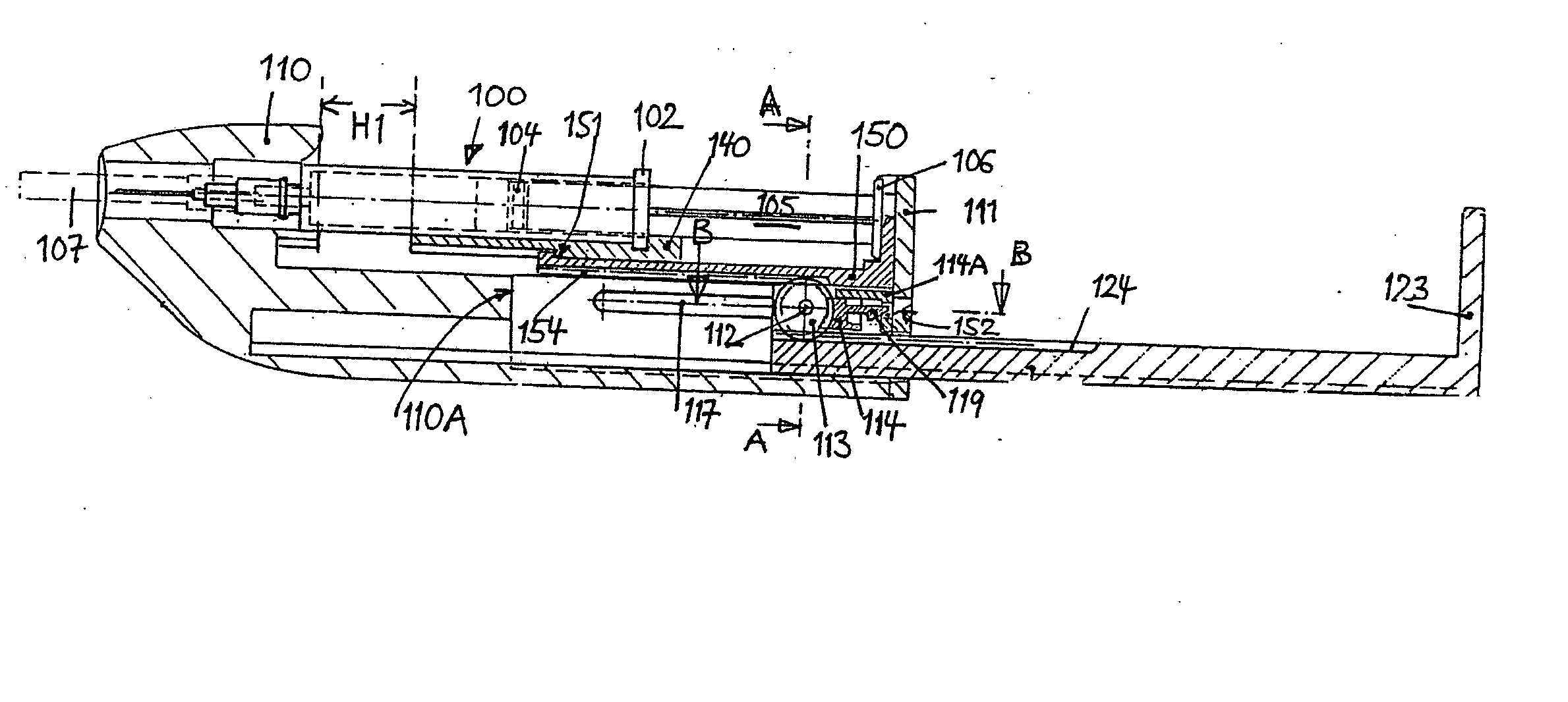
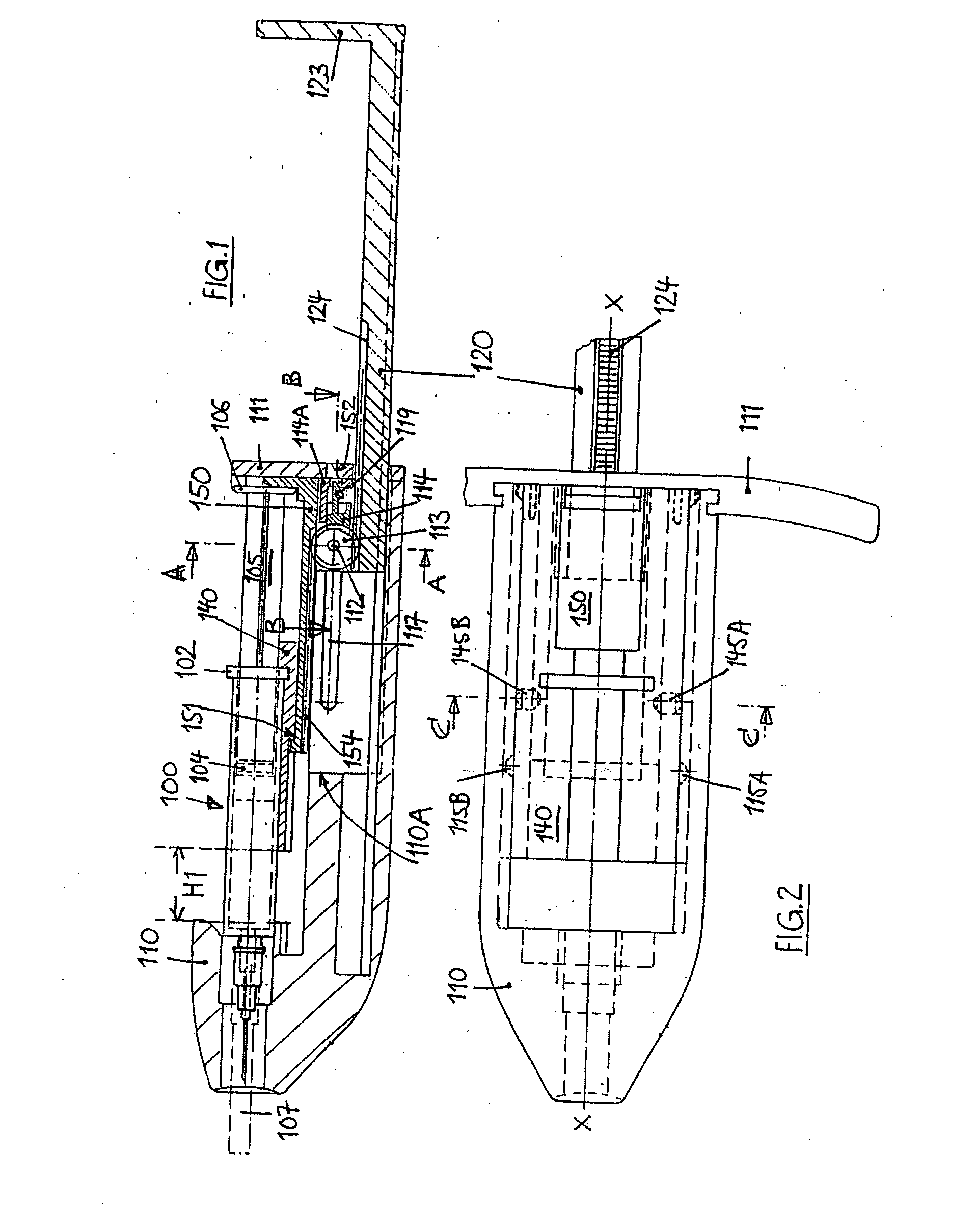
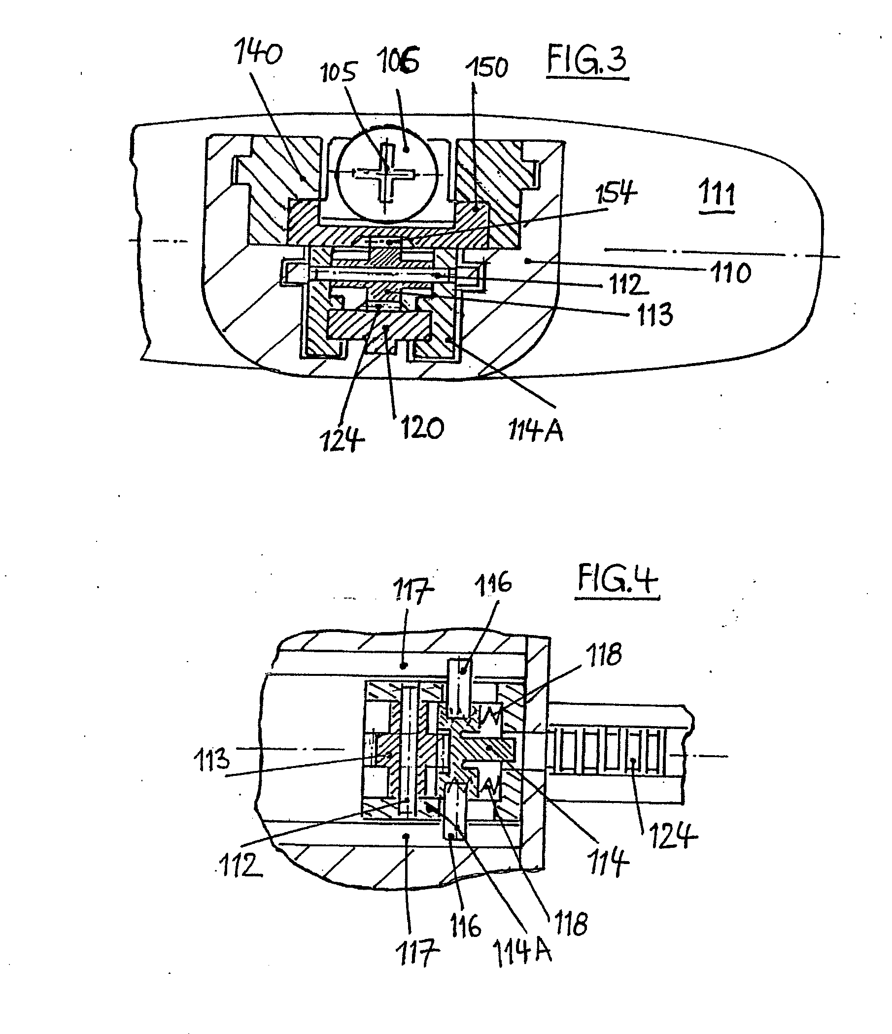
[0086] Four illustrative embodiments are described below. In all of the illustrative embodiments, the basic structure of the injection device is as follows:

[0087] The syringe with plunger, plunger rod and cannula with needle is inserted into a syringe holder, with the aid of which the insertion stroke H1 is effected, i.e. the insertion of the needle into the injection site. For this purpose, the syringe holder is mounted in an axially displaceable manner in a housing. To actuate the syringe after the insertion stroke, i.e. to inject the medicament, a ram is used which is mounted displaceably relative to the syringe holder and which acts on the plunger of the syringe (injection stroke H2). Syringe holder and ram are coupled releasably to one another in such a way that the injection stroke H2 begins immediately after the insertion stroke H1, i.e. during the insertion stroke H1 the syringe holder and ram are rigidly connected to one another and move forward together in the housing, wh...


PUM


Abstract

An injection device for a syringe, having a syringe body, a cannula with a needle, a plunger with a plunger rod, and an injection carriage for displacing the syringe body and the plunger, comprises at least one actuating element that acts on the injection carriage to carry out the injection procedure. The actuating element (120, 220, 320) cooperates with components which withdraw the needle (108, 208, 308) from the puncture site once the injection procedure has been completed, using a return stroke (H3) that is applied to the injection carriage. A single, targeted linear movement inserts the needle to a defined depth, injects the medicament and, once the injection has been completed, produces a return stroke which allows the needle to be withdrawn into the housing and thus out from the puncture site. The injection device is advantageously equipped with additional components which produce a delay (TV) between the completion of the injection stroke (H2) and the start of the return stroke (H3). The advantage of said delay is that the pressure that has been produced in the subcutaneous tissue by the injection of the medicament can subside before the needle is withdrawn, thus preventing to a great extent the penetration of the medicament into the insertion channel of the needle. A volume adapter (410) can advantageously be used to predetermine the injection stroke (H2) and thus the quantity of a medicament that is administered during the course of the injection stroke (H2).

Description

TECHNICAL BACKGROUND [0001] Many injection devices are known which allow an inserted syringe to be positioned in such a way as to permit simple insertion into the skin, to the required depth, and injection of the medicament, without the syringe being maneuvered directly by hand. Such an injection device in every case has the purpose of improving the safety of the injection and also the handling comfort, so that injections that are often needed on a daily basis or in some cases even several times a day can be carried out independently by all patients themselves, even without specific training, which also represents a considerable saving in costs. PRIOR ART [0002] Injection devices are known in which, in order to increase comfort and safety, an automatic sequence of insertion of the syringe needle and subsequent injection is carried out, for example as is known from EP 1 233 801. After the injection has been completed, the injection device has to be moved away from the puncture site b...

Claims


Application Information

Patent Timeline
Patent Type & Authority Applications(United States)
IPC IPC(8): A61M5/00A61M5/20A61M5/315A61M5/32A61M5/46
CPCA61M5/20A61M5/2033A61M5/315A61M5/326A61M2005/206A61M2005/208A61M2005/2086A61M2005/3152A61M2205/581A61M5/46
Inventor WEBER
Owner BAYER INTELLECTUAL PROPERTY GMBH
Learn More