Diode-laser-pumped ultraviolet and infrared lasers for ablation and coagulation of soft tissue

a laser and ultraviolet light technology, applied in laser surgery, medical science, surgery, etc., can solve the problems of limited industrial and military uv spectrum, limited dpl in uv spectrum about (210 to 360) nm, and limited dpl output power

Inactive Publication Date: 2006-11-16
NEW VISION
View PDF9 Cites 56 Cited by
  • Summary
  • Abstract
  • Description
  • Claims
  • Application Information

AI Technical Summary

Problems solved by technology

The recent development of high-power (larger than 20 W) diode array promotes the high-power DPL technology for practical applications, which, however, are limited to industrial and military.
Due to the technical difficulty and lack of new applications, DPL's in the UV spectrum of 0.2 to 0.4 microns have not been developed.
The available output power of DPL in UV spectrum about (210 to 360) nm is limited to less than about (0.1 to 0.5) W due to the low conversion efficiency of nonlinear crystals which convert the near IR to a green and then to a UV output.
Furthermore, the DPL UV laser disclosed in Lin-679 is limited to corneal reshaping which requires a UV wavelength of (193 to 213) nm, much shorter than the 265 nm disclosed in this invention, and it is very difficult to obtain the required power level for corneal reshaping.
Similar to the earlier discussions for DPL in UV, the conversion efficiency of DPL in mid-IR is also limited to about (2%-3%) due to the lack of high-power diode array and the rather low emission efficiency in the laser crystals of Er:dopped, which is about 2 to 5 times lower than that of Nd-dopped crystals, such as Nd:YAG or Nd:YLF.
Mid-IR laser of Er:Cr:YSGG (at 2780 nm) was disclosed in the prior arts of U.S. Pat. Nos. 5,342,198; 6,086,367; 6,567,582, however, it used a standard commercially available flash-lamp-pumped (FLP) system and was limited to dental applications, where much higher power of about 1 to 6 W is required.

Method used


Image

  • Diode-laser-pumped ultraviolet and infrared lasers for ablation and coagulation of soft tissue
  • Diode-laser-pumped ultraviolet and infrared lasers for ablation and coagulation of soft tissue
  • Diode-laser-pumped ultraviolet and infrared lasers for ablation and coagulation of soft tissue

Examples


Embodiment Construction

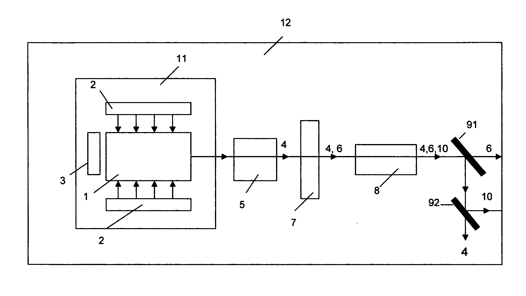
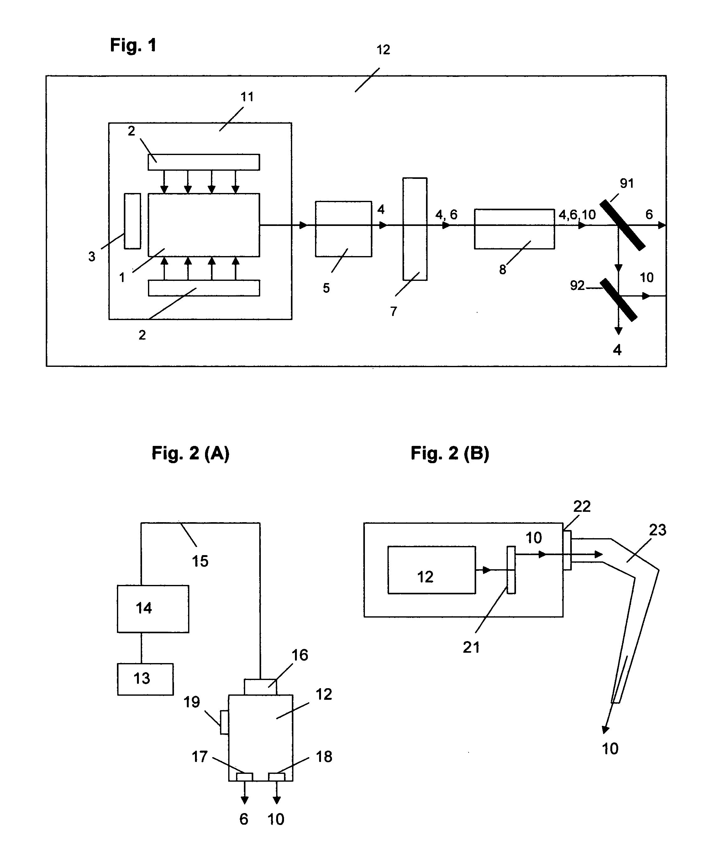
[0030] As shown in FIG. 1 (A), a lasing crystal 1 is side-pumped by a pair of diode-laser array 2 and reflected by a back optics 3 to produce an output beam 4 which is mode controlled by a Q-switch device 5 for pulse output. The fundamental beam 4 having an IR wavelength at about 1064 nm or 1053 nm, for lasing crystal Nd:YAG or Nd:YLF, respectively, is converted to a green output 6 (at 532 or 527 nm) via a second harmonic generation nonlinear crystal (SHC) 7 which is further converted to a UV output 10 (at about 266 or 263 nm) via a fourth-harmonic generation crystal (FHC) 8 which may be separated from the IR and green by a pair of dichromatic optics 91 and 92. We also define the laser cavity 11 and the integrated unit 12.

[0031] The preferred specifications of materials used in FIG. 1 include: (1) back surface of the lasing crystal 1 is anti-reflection (AR) coated at the fundamental wavelength (IR), and its front (output) surface is partially reflecting (about 2% to 10%) to the IR;...


PUM


Abstract

Method and systems for eye surgery for the treatment of presbyopia, ocular hypertension and glaucoma and other soft tissue surgeries are disclosed. System design parameters of lasing crystals (Nd:YAG, Nd:YLF, Er:YAG and Er:YSGG), nonlinear crystals (KTP, BBO, LBO), laser cavity configuration and energy delivery means are disclosed for diode-laser-pumped lasers with output wavelength at UV (263 or 266 nm), green (527 or 523 nm), and mid-IR (2.78 or 2.94 microns). Dual function of ablation and coagulation is proposed by a mode control means. The preferred diode-laser includes a wavelength at about 0.75 to 0.98 microns with power about 15 to 40 W and used in a side-pumping configuration to generate UV or IR having an energy per pulse about 3 to 30 mJ, power of about 0.1 to 1.5 W and operated at free running mode (IR laser) or pulsed mode (UV laser).

Description

BACKGROUND OF THE INVENTION 1. Field of the Invention [0001] This invention relates to methods and systems for the treatment of presbyopia and glaucoma and for use in microsurgery of soft tissue of other parts of human body. This invention also relates to the generation of ultraviolet and infrared coherent light by diode-laser-pumped technology. 2. Prior Art [0002] The first mini-size semiconductor diode pumped laser (DPL) was demonstrated in the early 1980 by Professor Yariv of Stanford University. Due to the available power of GaAs diode laser, the output of the mini-DPL was only few miliwatt (mW) at a near infrared (IR) wavelength (1064 nm). The recent development of high-power (larger than 20 W) diode array promotes the high-power DPL technology for practical applications, which, however, are limited to industrial and military. Low power DPL about (1 to 10) mW has been used for medical uses such as retina treatment of an eye, which however, are limited to a green spectrum (532 n...

Claims


Application Information

Patent Timeline
Patent Type & Authority Applications(United States)
IPC IPC(8): A61B18/18
CPCA61B18/20A61B18/201A61F9/008A61F2009/00895A61F9/00821A61F2009/00863A61F2009/00891A61F9/00808
Inventor LIN, J. T.
Owner NEW VISION
Why Eureka
Try Eureka