Conductive fluid bridge electrosurgical apparatus

a technology of electrosurgical apparatus and fluid bridge, which is applied in the field of electrosurgical apparatus, can solve the problems of reducing affecting the safety of electrosurgical instruments, so as to achieve better visibility and restrict the size of the fluid bridge

Inactive Publication Date: 2006-11-16
ARTHROCARE
View PDF99 Cites 156 Cited by
  • Summary
  • Abstract
  • Description
  • Claims
  • Application Information

AI Technical Summary

Benefits of technology

[0015] Advantageously, since the pinhole of the present instrument restricts the amount of fluid forming the fluid bridge during use, the size of the fluid bridge is restricted. Thus with the vacuum suction inlet located on the instrument, in use the fluid bridge is maintained regardless of the orientation of the instrument with respect to the tissue, without flooding the electrodes and/or the tissue. Accordingly the present instrument is usable to treat tissue for any orientation of the electrodes relative to the tissue, without loss of plasma generation. Additionally the instrument can be used in procedures wherein it is neither desirable nor possible to flood the tissue. Further, since the pinhole restricts the amount of

Problems solved by technology

With these instruments, for certain procedures it is a problem to maintain an unbroken conductive fluid path between the electrodes during use.
In these procedures because the distal end of the instrument is positioned either higher than the proximal end and/or the electrodes are turned up during use, gravity causes the fluid to flow downwards and away from the electrodes, thus breaking the fluid path.
With the breaking of the fluid path, the instrument may exhibit undesirable therm

Method used


Image

  • Conductive fluid bridge electrosurgical apparatus
  • Conductive fluid bridge electrosurgical apparatus
  • Conductive fluid bridge electrosurgical apparatus

Examples


Embodiment Construction

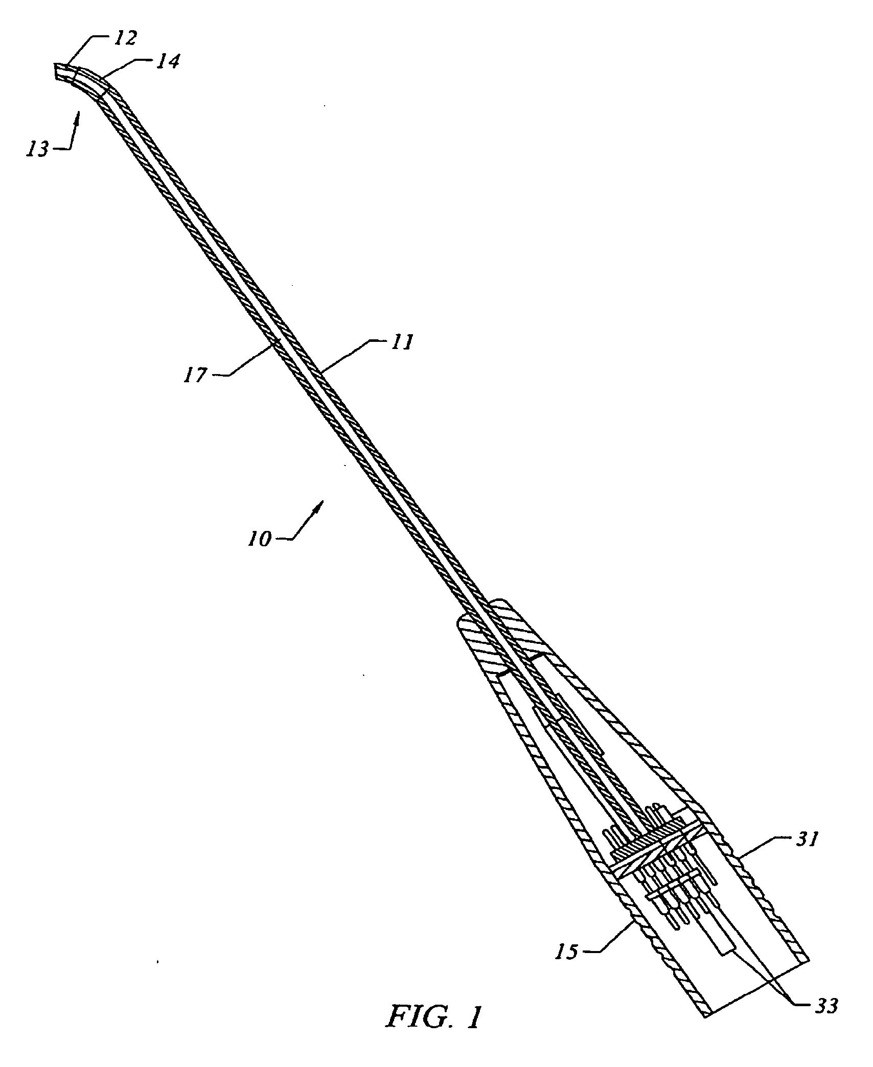
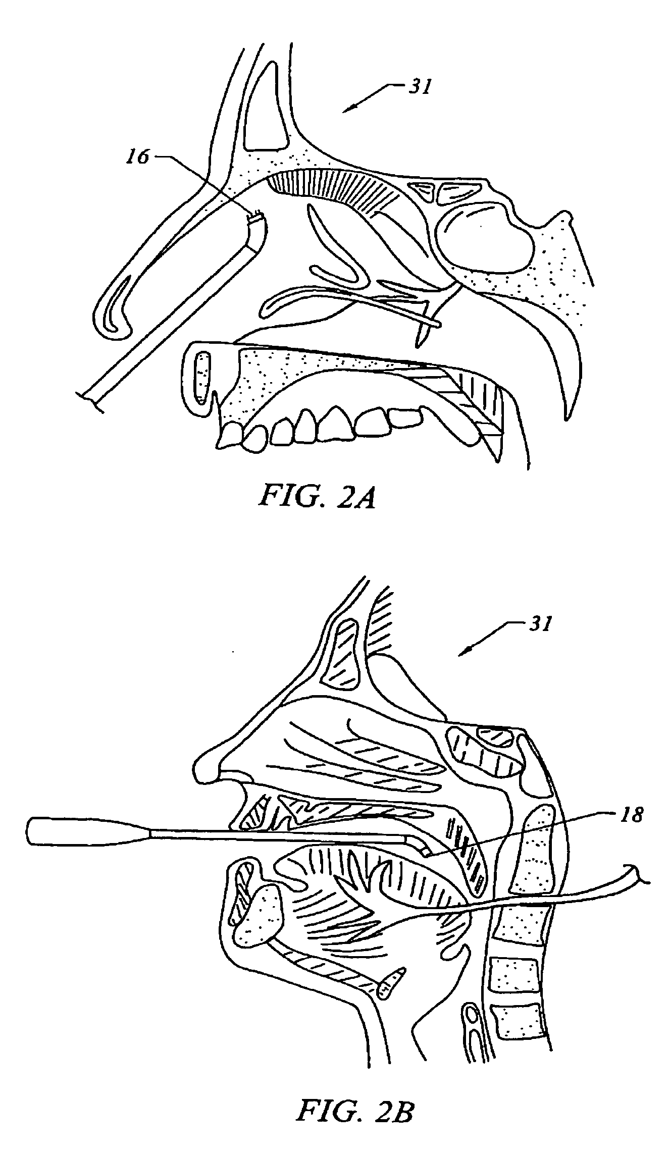
[0022] Embodiments of the present invention are illustrated in FIGS. 1, 2a, 2b, 4 and 5 wherein a pinhole is provided for controlling the supply of fluid to form a fluid bridge between the electrodes. In the embodiments illustrated in FIGS. 1 and 4, the instrument includes an elongated member (11) having a proximal end portion (15, 31) that includes electrical terminals (33) for connecting the active and return electrodes (12, 14, 34, 36) to a high frequency voltage supply (35).

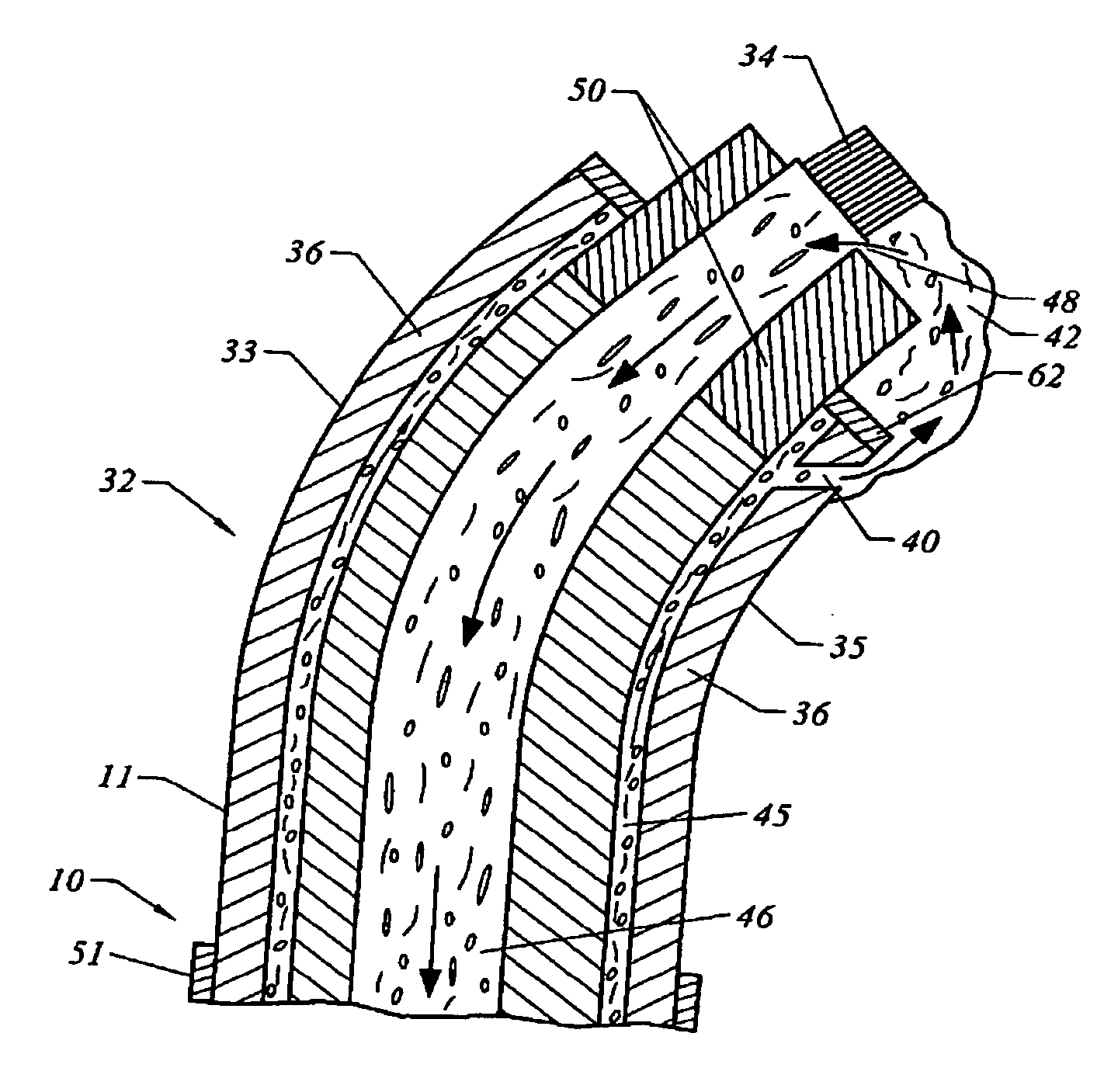
[0023] In the embodiment illustrated in FIG. 5, the instrument (10) comprises elongated member (11) having a distal end portion (32); an active electrode (34) and a return electrode (36) disposed on the distal end portion; and at least one pinhole (40) defined on the distal end portion for forming an conductive fluid bridge (42) between the active and return electrodes. Also in the embodiment of FIG. 5, the distal end portion (32) is a generally curved member having an outer curved surface (33) and an inner ...


PUM


Abstract

An electrosurgical apparatus for treating body tissue, comprising an active and a return electrode, a vacuum inlet located near the active electrode, and at least one pinhole defined on the apparatus near the return electrode that is adapted to provide a conductive fluid bridge between the active and return electrodes during use regardless of the orientation of the electrodes relative to the tissue, without flooding the electrodes or the tissue. Also, a method and system of performing a dry field surgical procedure comprising applying ablative energy to a target tissue wherein the target tissue is not flooded or submerged in electrically conductive fluid; and maintaining a fluid bridge between the electrodes regardless of the orientation of the shaft. Advantageously, since the conductive fluid bridge is maintained for any orientation of the electrodes relative to the tissue without flooding, the instrument can be used to treat tissue from any orientation without breaking the fluid bridge.

Description

BACKGROUND [0001] 1. Field of the Invention [0002] This invention relates to an electrosurgical apparatus comprising an active electrode, a return electrode, and a conductive fluid bridge maintained between the electrodes during use regardless of the orientation of the apparatus. [0003] 2. Description of the Prior Art [0004] In some electrosurgical procedures an instrument, as illustrated for example in FIG. 1, comprising an active electrode (12) and a return electrode (14) is used to treat body tissue. Treatment includes without limitation coagulation, cutting, ablating, abrading or puncturing the tissue. In various embodiments, generating plasma between the electrodes and applying the plasma to the tissue, without passing a current through the tissue, effects treatment. Examples of these instruments and their use in electrosurgical procedures are described in U.S. Pat. Nos. 5,683,366 and 6,235,020 herein incorporated by reference. In various embodiments, the conductive fluid path ...

Claims


Application Information

Patent Timeline
IPC IPC(8): A61B18/14
CPCA61B18/1485A61B2018/1213A61B2218/007A61B2218/002A61B2218/003A61B2018/1472
Inventor DAHLA, ROBERT H.
Owner ARTHROCARE
Why Eureka
Try Eureka