Silt trap for water and gas valve boxes

a technology for gas valve boxes and silt traps, which is applied in the direction of valve operating devices/release devices, drawing-off water installations, transportation and packaging, etc., can solve the problems of emergency crews having difficulty obtaining access to the operating stems of valves, substantial damage to surrounding properties, and a large amount of difficulty

Inactive Publication Date: 2006-11-23
B & K MFG COMPANY L L C
View PDF10 Cites 7 Cited by
  • Summary
  • Abstract
  • Description
  • Claims
  • Application Information

AI Technical Summary

Benefits of technology

[0010] Another object of the invention is to provide such a device which will trap any sediment tending to fall in around a valve nut in a valve box, which device can be simply pulled out and emptied periodically and which will not allow sediment to fall inside the box during removal.

Problems solved by technology

As well-known in the prior art, when a water line becomes broken, very serious damage can result from water gushing out of the break and flooding adjacent residences or other buildings, doing substantial damage to the surrounding properties.
In some cases, emergency crews have difficulty obtaining access to the operating stems of the valves because the valve box or enclosure has become filled up, as has been described.
Typically, a good deal of difficulty is experienced in digging out or extracting debris from the underground enclosure which, in turn, delays the time before the emergency can be corrected, and the valve or valves are shut off to stop water coming out of the break.

Method used


Image

  • Silt trap for water and gas valve boxes
  • Silt trap for water and gas valve boxes
  • Silt trap for water and gas valve boxes

Examples


Embodiment Construction

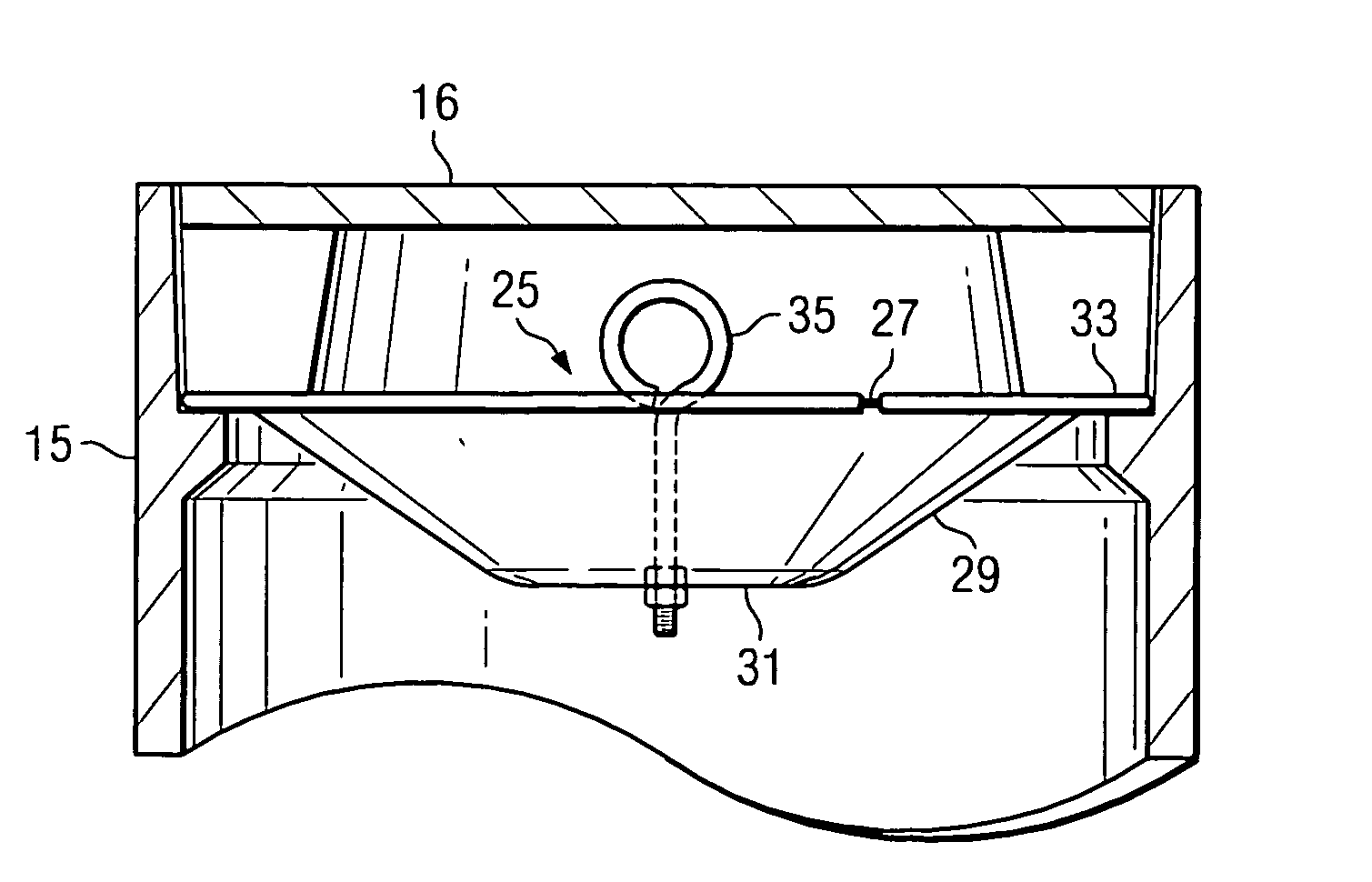
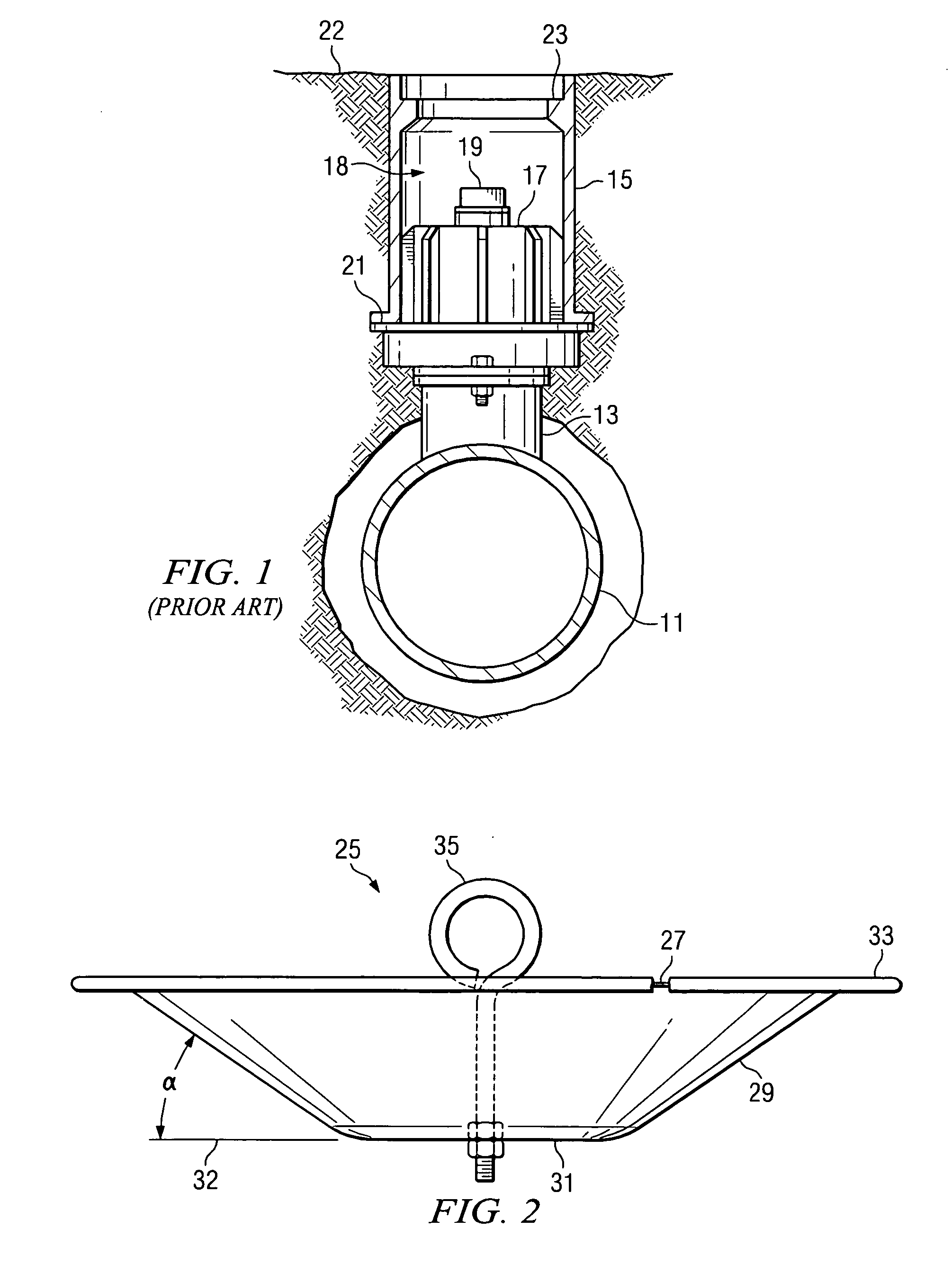
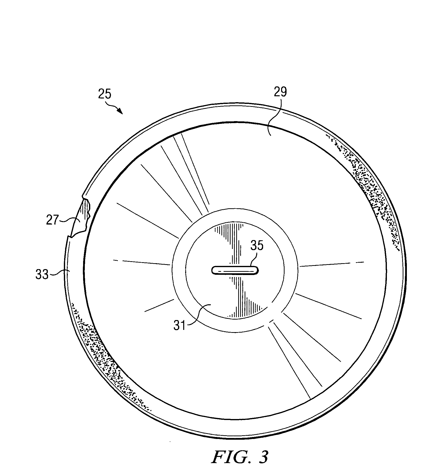
[0021] Underground valves of the type under consideration will be well familiar to those skilled in the relevant waterworks and natural gas industries. As has been briefly described, the invention deals with a device and method whereby access to the end of the valve stem at the bottom of the valve box may be more easily assured, as well as for preventing the buildup of silt, debris or other material in the bottom of the valve box with the passage of time.

[0022] Typically, a valve box of the type under consideration may have a size which is in the range of 6 inches to 12 inches in diameter, depending upon the size of the water main and valve with which it is operated. In one embodiment, the silt trap of the present invention is designed to fit a standard 7½ inch cast iron water and gas valve box. However, it will be readily appreciated that the device of the invention can be provided in convenient sizes to fit all standard valve boxes, both water and gas. Typically, the valve in que...


PUM


Abstract

A silt trap is shown which provides easy access to the end of a valve stem of a valve in a buried water main having a valve box which extends from the valve to the surface. The trap is a tapered bowl having a centrally located I-bolt for removal. The lip of the bowl is covered by a U-shaped gasket which seals around the entire periphery of the bowl lip. The device traps silt and other debris and can be easily removed for dumping without allowing debris to fall into the valve box.

Description

CROSS-REFERENCE TO RELATED APPLICATIONS [0001] This application claims priority from a provisional application Ser. No. 60 / 683,326, filed May 23, 2005.BACKGROUND OF THE INVENTION [0002] 1. Field of the Invention [0003] The present invention relates generally to underground access boxes containing underground valves, such as those being commonly employed in municipal water and gas systems utilizing lines that are buried underground. [0004] 2. Description of the Prior Art [0005] When underground lines are laid, it is generally necessary to have one or more underground valves in the lines for use in controlling the flow of the material through the lines. For example, in the case of municipal water works distribution system, many miles of water lines are buried in the streets and right of ways in order to serve municipal customers. Included in these miles of pipelines there may be hundreds, if not thousands, of valves. These are typically gate valves to control the flow of water in the ...

Claims


Application Information

Patent Timeline
Patent Type & Authority Applications(United States)
IPC IPC(8): F16L5/00
CPCF16K31/46E03B9/10Y10T137/7021
Inventor GREEN, JOHN BOBBY
Owner B & K MFG COMPANY L L C
Why Eureka
Try Eureka